
Automotive
Does Brake Fluid Go Bad?

Yes, brake fluid can go bad over time. Brake fluid is an essential component of your vehicle’s braking system, and its performance is crucial for safe and effective braking. However, like any fluid, it can degrade or become contaminated, leading to potential brake system issues. It’s important to understand the factors that affect brake fluid, how to recognize when it’s gone bad, and how to maintain it properly.
How Brake Fluid Degrades
1. Absorption of Moisture
- Brake fluid is hygroscopic, meaning it absorbs moisture from the air over time. Moisture can enter the brake fluid through small seals and components in the brake system. As brake fluid absorbs water, its boiling point decreases, which can lead to vapor lock or brake fade during hard braking. This can significantly impair braking performance and safety.
- Water contamination also accelerates corrosion inside the brake lines, rotors, and calipers, which can cause significant damage to the brake system.
2. Heat Exposure
- Brake fluid is exposed to high temperatures during normal driving, especially when braking heavily. Excessive heat can break down the fluid’s chemical properties, leading to reduced effectiveness. Over time, heat degradation can cause the fluid to lose its ability to lubricate and protect the brake system components.
3. Age of the Fluid
- Even if brake fluid doesn’t appear contaminated or dirty, over time, it can lose its effectiveness due to age. Brake fluid typically needs to be replaced every 2 years or 24,000 miles (depending on the vehicle manufacturer’s recommendations), even if it doesn’t show visible signs of contamination.
4. Contamination from Other Fluids
- In some cases, brake fluid can become contaminated with other automotive fluids, such as oil or power steering fluid, especially if there’s a malfunction or leak in the brake system. This can alter the brake fluid’s chemical composition and reduce its performance.
Signs That Brake Fluid Has Gone Bad
1. Soft or Spongy Brake Pedal
- If your brake pedal feels soft or spongy when pressed, it could be a sign that the brake fluid has absorbed moisture, causing air bubbles to form in the brake lines. This air can compress when you press the brake pedal, leading to reduced braking power.
2. Brake Fluid Color
- Fresh brake fluid is typically clear or light yellow. Over time, as it absorbs moisture and becomes contaminated, it may turn dark brown or black. A significant change in color could indicate that the fluid is old or contaminated and should be replaced.
3. Brake Fade or Poor Braking Performance
- If you notice that your braking performance has deteriorated, such as longer stopping distances or difficulty stopping the vehicle, it may be due to degraded brake fluid. The fluid may no longer be able to effectively transfer force from the brake pedal to the brake components.
4. Braking System Warning Light
- Some vehicles are equipped with a brake system warning light that will activate if there’s an issue with the brake fluid, such as low levels or contamination. If this light comes on, it’s essential to have the brake fluid checked and replaced if necessary.
How to Maintain Brake Fluid
1. Regularly Check Brake Fluid Levels
- It’s important to regularly check the brake fluid level to ensure it’s within the recommended range. If the fluid is low, it could be a sign of a leak, and you should have your brake system inspected.
2. Replace Brake Fluid Periodically
- Follow your vehicle manufacturer’s recommendations for brake fluid replacement. Typically, brake fluid should be replaced every 2 years or 24,000 miles, but this may vary depending on the type of brake fluid (DOT 3, DOT 4, DOT 5, or DOT 5.1) and the manufacturer’s guidelines.
3. Use the Right Brake Fluid
- Always use the recommended type of brake fluid for your vehicle. Different vehicles require different brake fluid specifications, and using the wrong type can cause damage to the brake system.
4. Brake Fluid Flush
- If your brake fluid is contaminated or has gone bad, a brake fluid flush is the best way to remove old fluid and replace it with fresh fluid. A brake fluid flush can be performed at an auto repair shop.
Conclusion
In conclusion, brake fluid does go bad over time, primarily due to moisture absorption, heat exposure, and contamination. As brake fluid degrades, its effectiveness diminishes, potentially leading to reduced braking performance or even brake system failure. It’s essential to maintain your brake fluid by checking it regularly, replacing it at the recommended intervals, and ensuring the right fluid is used for your vehicle.
If you notice signs such as a spongy brake pedal, dark brake fluid, or poor braking performance, it’s important to have your brake fluid checked and replaced immediately to maintain the safety and reliability of your vehicle’s braking system.
Also Check:
• Does Brake Fluid Remove Car Paint
• Does Brake Fluid Brand Matter
• Does Brake Cleaner Remove Rust

Activating a Karr security system is a crucial step in ensuring your vehicle remains protected against theft and unauthorized access. Karr is known for its reliable car alarm systems, keyless entry features, and immobilizers. Proper activation allows the system to function optimally, providing peace of mind to vehicle owners. This guide will cover all aspects of activating Karr security systems, including preparation, installation verification, programming, troubleshooting, and best practices for use.
understanding karr security systems
Karr security systems are designed to provide comprehensive vehicle protection through a combination of alarms, immobilizers, and remote control functionalities. These systems typically include:
- Car Alarm: Detects unauthorized entry or movement of the vehicle.
- Keyless Entry: Allows remote locking and unlocking of the vehicle.
- Immobilizer: Prevents the vehicle from starting without the proper key or remote signal.
- Shock Sensors: Detects impacts or vibrations to trigger the alarm.
- Remote Control: Enables activation and deactivation of the system from a distance.
Understanding the components of your Karr system is essential before attempting activation, as different models may have varying features and steps for programming.
prerequisites for activating karr security systems
Before activating your Karr security system, ensure the following:
- Battery Power: Verify that the vehicle’s battery and the remote control battery are fully charged.
- Correct Installation: Ensure that the system is installed correctly and all wires are connected according to the manufacturer’s instructions.
- User Manual: Have the system’s user manual available for reference, as activation procedures can differ between models.
- Vehicle Readiness: Make sure doors, hood, and trunk are closed, and the ignition is in the OFF position.
- Remote Control: Ensure the remote control is compatible with the installed system.
Meeting these prerequisites ensures that the activation process is smooth and avoids unnecessary errors.
locating the activation button or switch
Most Karr security systems have a hidden activation button or switch inside the vehicle, which is used to program the system and pair the remote control. Common locations include:
- Under the dashboard near the steering column.
- Inside the center console or glove compartment.
- Near the fuse box or ignition wiring.
Refer to the system’s manual for the exact location, as pressing the correct button is necessary to enter programming mode.
entering programming mode
To activate your Karr security system, you must first enter programming mode. The steps generally include:
- Turn the Ignition On: Insert the key into the ignition and turn it to the ON position without starting the engine.
- Press the Activation Button: Press and hold the hidden activation button until the system’s LED indicator flashes or a sound confirms entry into programming mode.
- Release the Button: Release the button once the system acknowledges the mode entry, often through one long beep or flashing lights.
Programming mode allows you to pair remote controls, set security options, and adjust system preferences.
pairing remote controls
Once in programming mode, the next step is pairing your remote controls to the Karr system:
- Press Remote Button: Press a specific button on the remote, usually the lock or unlock button, to transmit its signal to the system.
- Confirmation: The system will acknowledge the pairing with a sound, flash, or LED indicator.
- Repeat for Additional Remotes: If you have more than one remote, repeat the pairing process for each device.
Successful pairing ensures that only authorized remotes can operate the system.
testing the karr system
After activation and pairing, it is essential to test the system:
- Lock and Unlock: Use the remote to lock and unlock the doors and verify that the alarm responds.
- Alarm Trigger: Activate the alarm manually to ensure it responds to shocks or unauthorized entry.
- Remote Range: Test the remote at various distances to confirm optimal signal transmission.
- Ignition Immobilizer: Attempt to start the vehicle without the remote to ensure the immobilizer is functioning correctly.
Testing confirms that the system is fully operational and provides maximum security.
troubleshooting common activation issues
During activation, you may encounter problems. Common issues include:
- Remote Not Pairing: Check battery power, ensure you are in programming mode, and verify compatibility with your Karr system.
- System Not Responding: Confirm correct wiring and that the vehicle’s battery is fully charged.
- False Alarms: Adjust shock sensor sensitivity settings to prevent accidental triggers.
- LED Indicator Not Flashing: Replace the system’s fuse or check connections to ensure power is reaching the control unit.
Following the manual and these troubleshooting steps resolves most common activation problems.
customizing system settings
After activation, you can customize Karr system settings to match your preferences:
- Shock Sensor Sensitivity: Adjust to prevent false alarms while maintaining protection.
- Alarm Duration: Set how long the alarm sounds when triggered.
- Remote Functions: Enable or disable features such as trunk release, panic button, or silent arm/disarm.
- Automatic Locking: Program doors to lock automatically after a specific time.
Customizing these settings ensures your security system meets your specific needs.
maintaining your karr security system
Proper maintenance helps keep your Karr system in peak condition:
- Battery Check: Regularly check the vehicle and remote batteries.
- Clean Components: Keep buttons, sensors, and wiring free from dust and moisture.
- Software Updates: If your system supports updates, install them as provided by the manufacturer.
- Professional Service: Periodically have a certified technician inspect the system to ensure functionality.
Routine maintenance prolongs the life of your security system and prevents malfunctions.
conclusion
Activating a Karr security system requires careful attention to installation, programming, and testing. By understanding the components, entering programming mode correctly, pairing remotes, and customizing settings, vehicle owners can maximize protection against theft and unauthorized access. Regular maintenance and troubleshooting ensure the system remains reliable over time, providing peace of mind and effective vehicle security. Following this guide allows users to confidently activate their Karr security systems and enjoy the full benefits of advanced car protection technology.
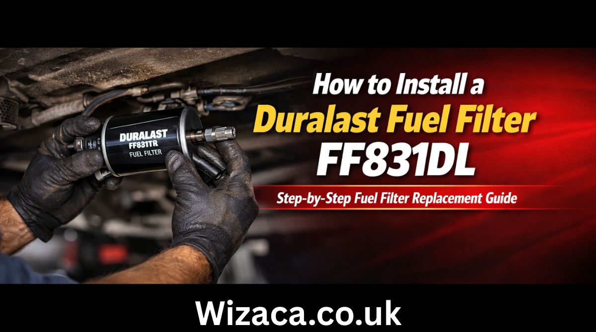
Learning how to install a Duralast fuel filter FF831DL properly is essential for maintaining your vehicle’s fuel system performance and engine efficiency. The Duralast Fuel Filter FF831DL is designed to trap dirt, rust particles, and other contaminants before they reach the fuel injectors or carburetor. Over time, fuel filters become clogged, restricting fuel flow and causing symptoms such as engine hesitation, poor acceleration, rough idling, or difficulty starting. Replacing the fuel filter at recommended intervals helps maintain proper fuel pressure and ensures smooth engine operation. Understanding the tools required, safety precautions, and correct installation steps will allow you to complete the task safely and effectively.
Understanding the Purpose of a Fuel Filter
Before focusing on how to install a Duralast fuel filter FF831DL, it is important to understand its function. Fuel travels from the fuel tank to the engine through fuel lines. During this process, contaminants such as debris, rust flakes, and sediment may enter the system. The fuel filter acts as a barrier, preventing these impurities from reaching sensitive engine components. A clogged filter reduces fuel flow, which can negatively affect performance and fuel economy. Replacing it restores proper flow and protects internal engine parts.
Identifying the Correct Location
The location of the fuel filter varies depending on the vehicle. In many cars and light trucks, the inline fuel filter is mounted along the fuel line under the vehicle, often near the fuel tank or along the frame rail. In some vehicles, it may be located inside the engine compartment. Before beginning installation, consult your vehicle’s service manual to identify the exact placement. Correct identification ensures safe access and efficient replacement.
Tools and Materials Needed
To successfully complete how to install a Duralast fuel filter FF831DL, gather necessary tools before starting. Common tools include safety gloves, protective eyewear, a jack and jack stands if access underneath is required, fuel line disconnect tools if applicable, wrenches, a container to catch spilled fuel, clean rags, and the replacement fuel filter. Having everything prepared reduces interruptions and increases safety.
Safety Precautions Before Starting
Fuel systems are pressurized, and gasoline is highly flammable. Before working on the fuel system, relieve fuel pressure. This can often be done by removing the fuel pump fuse and running the engine until it stalls. Turn off the ignition afterward. Disconnect the negative battery terminal to reduce the risk of sparks. Work in a well ventilated area away from open flames or heat sources. Keep a fire extinguisher nearby as an added safety measure.
Raising the Vehicle if Necessary
If the fuel filter is mounted underneath the vehicle, lift the vehicle using a jack and secure it with jack stands on a stable surface. Never rely solely on a jack for support. Ensure the vehicle is stable before crawling underneath. Safety during this stage is critical when learning how to install a Duralast fuel filter FF831DL.
Locating the Existing Fuel Filter
Once access is available, locate the existing inline fuel filter. It is typically cylindrical and connected between two sections of fuel line. Note the direction of fuel flow indicated by an arrow on the old filter. The new filter must be installed in the same orientation to ensure proper function.
Preparing for Removal
Place a container beneath the filter to catch any residual fuel. Even after relieving pressure, some fuel may remain in the lines. Use clean rags to minimize spillage. If your vehicle uses quick connect fittings, use the appropriate disconnect tool to release the fuel lines. For threaded fittings, use the correct size wrench to avoid damaging the fittings.
Removing the Old Fuel Filter
Carefully disconnect the fuel lines from both ends of the old filter. Avoid bending or twisting the lines excessively. Once disconnected, remove the mounting bracket or retaining clip holding the filter in place. Gently remove the old filter and allow any remaining fuel to drain into the container. Dispose of the old filter according to local environmental regulations.
Comparing the New Filter
Before installation, compare the new Duralast fuel filter FF831DL to the old one. Ensure the inlet and outlet fittings match in size and design. Confirm that the overall length and connection style are identical. This step prevents installation errors and ensures compatibility.
Installing the New Fuel Filter
Position the new filter in the mounting bracket with the arrow indicating fuel flow pointing toward the engine. This orientation is crucial. Secure the filter in its bracket firmly but do not overtighten to avoid damage. Reconnect the fuel lines to the appropriate ends. If using quick connect fittings, push until you hear or feel a click indicating secure attachment. For threaded fittings, tighten them carefully without cross threading.
Rechecking Connections
After installation, double check all connections to ensure they are tight and properly seated. Loose fittings can lead to fuel leaks. Inspect the mounting bracket to confirm the filter is stable and not contacting other components.
Restoring Fuel System Pressure
Reconnect the negative battery terminal. Reinstall the fuel pump fuse if it was removed. Turn the ignition key to the on position for a few seconds without starting the engine. This primes the fuel system and restores pressure. Turn the key off and repeat this process two or three times to ensure proper pressure buildup.
Checking for Leaks
Start the engine and inspect the area around the filter for any signs of leakage. Look closely at both connections and the body of the filter. If you notice fuel dripping or smell gasoline strongly, turn off the engine immediately and tighten connections as needed. Ensuring there are no leaks is an essential part of how to install a Duralast fuel filter FF831DL safely.
Lowering the Vehicle
If the vehicle was lifted, carefully remove the jack stands and lower it back to the ground once you confirm there are no leaks. Ensure all tools and containers are removed from underneath before lowering.
Testing Vehicle Performance
After installation, take the vehicle for a short test drive. Pay attention to acceleration, idle smoothness, and overall responsiveness. A properly installed new fuel filter should improve fuel flow and may resolve previous performance issues related to fuel restriction.
Maintenance Interval
Fuel filters typically require replacement every 20000 to 40000 miles, depending on manufacturer recommendations and driving conditions. Regular replacement prevents fuel system damage and maintains efficiency. Check your vehicle’s maintenance schedule for specific guidance.
Common Mistakes to Avoid
When learning how to install a Duralast fuel filter FF831DL, avoid skipping the pressure relief step. Never install the filter backward. Do not overtighten fittings, as this can strip threads or damage lines. Avoid working near open flames. Ensure the vehicle is securely supported if raised.
Benefits of Proper Installation
Correct installation ensures consistent fuel pressure, better engine performance, improved fuel efficiency, and reduced strain on the fuel pump. A clean filter helps protect injectors from clogging and extends the life of the fuel system.
Final Thoughts
Understanding how to install a Duralast fuel filter FF831DL allows vehicle owners to perform essential maintenance safely and effectively. By following proper safety precautions, relieving fuel pressure, carefully removing the old filter, installing the new filter in the correct orientation, checking for leaks, and testing performance afterward, you can maintain a reliable and efficient fuel system. Regular inspection and timely replacement of the fuel filter help ensure smooth engine operation and long term vehicle reliability.
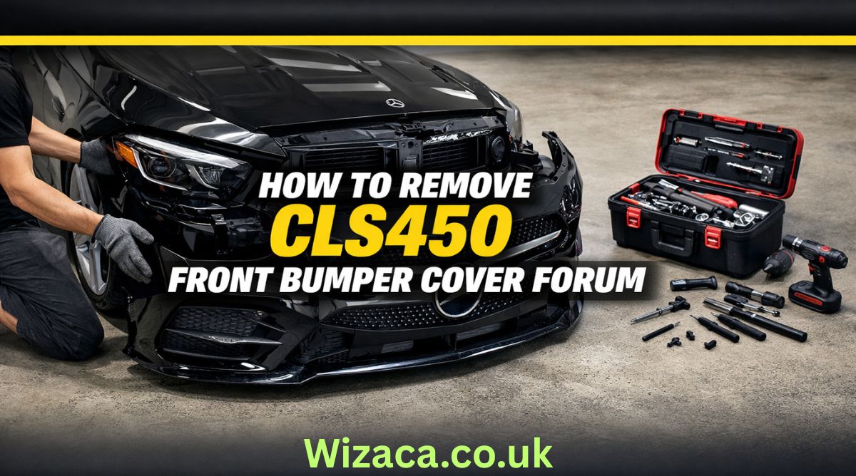
If you are searching for how to remove cls450 front bumper cover forum discussions, you are likely looking for detailed, practical guidance from owners and enthusiasts who have already performed the job. The CLS450 is part of the luxury CLS lineup from Mercedes-Benz, and while it offers refined styling and advanced technology, even premium vehicles occasionally require maintenance, repairs, or cosmetic upgrades. Removing the front bumper cover may be necessary for tasks such as replacing a damaged grille, installing a new sensor, repairing impact damage, upgrading lighting components, or repainting the bumper.
The Mercedes-Benz CLS450 features a modern front fascia design with integrated sensors, parking assistance systems, and sleek LED lighting. Because of this complexity, removing the bumper cover requires patience, the correct tools, and an understanding of how the components are assembled. Many forum users emphasize taking your time and documenting each step with photos to ensure smooth reinstallation.
Understanding the CLS450 Front Bumper Structure
Before starting the removal process, it is important to understand how the bumper is constructed. The CLS450 front bumper consists of a plastic outer cover attached to a reinforced internal structure. The cover is secured with screws, bolts, plastic clips, and fasteners along the top, bottom, and inside the wheel wells.
Modern models often include integrated components such as parking sensors, radar units for driver assistance systems, air intake ducts, and fog light housings. Disconnecting these properly is essential to prevent damage.
Forum discussions frequently highlight that the bumper cover is not extremely heavy, but it is wide and somewhat flexible. Having a second person assist during removal helps avoid bending or scratching the painted surface.
Tools Required for the Job
When reviewing how to remove cls450 front bumper cover forum advice, most users recommend gathering the proper tools before beginning. Typically, you will need a socket wrench set with metric sockets, a Torx bit set, plastic trim removal tools, a flathead screwdriver, and possibly a Phillips screwdriver. A trim clip removal tool is especially helpful to avoid breaking plastic fasteners.
It is also recommended to have a soft blanket or foam pad ready to place the bumper cover on once removed. This prevents paint scratches or scuffs.
Safety gloves are useful to protect your hands from sharp plastic edges or metal brackets. Good lighting is important as well, especially when working inside the wheel arches.
Preparing the Vehicle
Preparation is a crucial step. Park the vehicle on a flat surface and engage the parking brake. Turning the steering wheel fully to one side provides better access to the wheel well fasteners. Some forum members suggest removing the front wheels entirely for maximum space, though this is optional.
Disconnecting the battery may be advisable if you will be unplugging electronic sensors or radar modules. This reduces the risk of triggering warning lights or short circuits.
Opening the hood allows access to the upper mounting points of the bumper cover. These are typically located along the radiator support area.
Removing the Upper Fasteners
Under the hood, you will find several screws or bolts securing the top edge of the bumper to the front support structure. Carefully remove these using the appropriate socket or Torx bit.
Forum users often recommend placing all removed hardware in labeled containers to keep track of different screw lengths and types. Losing or mixing up fasteners can complicate reinstallation.
Once the upper bolts are removed, the bumper cover will still be secured at the sides and bottom.
Detaching Wheel Well Fasteners
Next, focus on the wheel wells. Inside each front wheel arch, there are multiple screws and plastic clips attaching the bumper cover to the fender liner.
Using a trim removal tool helps avoid damaging the clips. Gently pull back the fender liner to expose hidden screws securing the side edges of the bumper.
Many forum contributors note that this area can be tight, so patience is essential. Avoid pulling forcefully, as the painted tabs connecting the bumper to the fender can break if stressed.
Removing Lower Screws and Splash Shield Connections
Underneath the vehicle, the bumper cover connects to the lower splash shield and undertray. Remove the screws or bolts securing these sections.
In some models, additional fasteners are positioned near the front lip or air dam. Carefully inspect the entire lower edge before attempting to pull the bumper away.
Failing to remove a hidden fastener can result in cracked plastic tabs.
Disconnecting Electrical Components
One of the most important steps mentioned in how to remove cls450 front bumper cover forum threads is properly disconnecting electrical connectors. The CLS450 often includes front parking sensors, a front camera, radar sensors for adaptive cruise control, and LED daytime running lights.
Once the bumper is partially loosened, gently pull it forward a few inches and reach behind to unplug connectors. Press the release tabs carefully and avoid yanking wires.
Labeling connectors with tape can help during reinstallation, especially if multiple plugs look similar.
Removing the Bumper Cover
With all fasteners removed and connectors unplugged, the bumper cover can be detached. This step is best done with assistance. Each person should hold one side and gently pull outward at the corners near the fenders to release the side clips.
After releasing the sides, carefully pull the bumper forward and away from the vehicle. Place it on a prepared soft surface to prevent damage.
Forum members frequently emphasize checking once more for any missed connectors or clips before fully separating the bumper.
Common Challenges and Troubleshooting
Some users report difficulty with stubborn clips near the headlights. Applying gentle outward pressure while lifting slightly can help release these tabs.
Another common issue involves broken plastic retaining clips. Replacement clips are relatively inexpensive and should be replaced if damaged to ensure secure reinstallation.
If warning lights appear after reinstallation, they may be related to improperly connected sensors. Double-check all electrical connections before assuming a more serious issue.
Reinstallation Tips
Reinstalling the bumper cover follows the reverse order of removal. Position the bumper carefully and reconnect all electrical connectors before fully securing it.
Align the side tabs with the fender slots and press firmly until they click into place. Install lower screws and splash shield fasteners first to support the bumper’s weight.
Next, secure the wheel well screws and clips, ensuring the fender liner is properly aligned. Finally, tighten the upper bolts under the hood.
Do not overtighten screws, as this can strip plastic mounting points.
When to Seek Professional Help
Although many enthusiasts successfully remove the bumper themselves, some situations warrant professional assistance. If your vehicle is equipped with advanced driver assistance systems requiring sensor recalibration, a certified technician may be necessary.
Complex radar units integrated into the front fascia sometimes require precise alignment after removal. Incorrect positioning can affect adaptive cruise or collision prevention systems.
Additionally, if the bumper removal is related to accident damage, hidden structural components may need inspection.
Importance of Forum-Based Knowledge
The phrase how to remove cls450 front bumper cover forum reflects the value of community knowledge. Owners who share firsthand experiences provide practical insights beyond official service manuals.
Forums often include photos, step-by-step walkthroughs, and troubleshooting tips that simplify complex procedures. Reading multiple threads before beginning can prepare you for unexpected challenges.
While official repair manuals from Mercedes-Benz offer precise specifications, community advice adds real-world perspective.
Safety Considerations
Always work in a well-lit, stable environment. Avoid rushing the process. Keep hardware organized and protect painted surfaces from scratches.
If lifting the vehicle for better access, use proper jack stands rather than relying solely on a hydraulic jack.
Take extra care with delicate components such as sensors and wiring harnesses.
Final Thoughts
Searching how to remove cls450 front bumper cover forum typically means you want a practical, experience-based explanation rather than a brief overview. Removing the front bumper cover on the Mercedes-Benz CLS450 is a manageable task for those with moderate mechanical skill and patience.
Understanding the bumper’s attachment points, carefully removing fasteners, disconnecting electronic components properly, and working methodically are key to success. With preparation and attention to detail, the process can be completed safely and efficiently.
Whether your goal is repair, customization, or maintenance, following structured guidance ensures that your CLS450 remains in excellent condition while avoiding unnecessary damage or complications.

Who is Diven Labollita? Biography, Career, and Updates

How Much is Juan Ibarra Worth? Net Worth and Earnings (2026)

activities brought to you by lookwhatmomfound lwmfcrafts

Does a Check Engine Light Fail Inspection?
How to Adjust U-Haul Mirrors for Safe Driving
How to Load a 10′ U-Haul Truck Efficiently
-

 Health1 week ago
Ingredients in Siwzozmix458 Safe to Use: Complete Safety Guide
-

 General2 weeks ago
9043415725: Unknown Number Details and Information
-

 General1 week ago
6042390192 Full Details and Information Explained
-
 Lifestyle3 days ago
activities brought to you by lookwhatmomfound lwmfcrafts
-

 General2 weeks ago
9313717320: Everything You Need to Know About This Number
-

 General1 week ago
6043953585: Official Contact Information
-

 Technology6 days ago
Download Software tgd170.fdm.97 New Release: Latest Version
-

 Home Decor3 days ago
look what mom found fathead wall graphic giveaway