
Blog
VT1000 Pitting Photo Examples: Causes, Identification, and Practical Insights
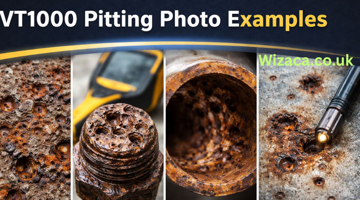
Pitting corrosion is one of the most insidious and localized forms of metal degradation observed in industrial materials. For those working with alloys such as the VT1000 series (a hypothetical high-performance alloy used in advanced industrial environments), understanding pitting corrosion is essential. Although this article does not present actual photos, it provides detailed descriptive examples of what pitting looks like and how practitioners interpret those visuals in real-world situations.
how it appears in photographs, what causes the specific patterns that engineers and inspectors observe, how to differentiate pitting from other surface damage, and how knowledge of these visual indicators informs material maintenance and failure prevention.
What Is Pitting Corrosion?
Pitting corrosion is a highly localized form of corrosion that leads to the formation of small holes or cavities on a metal surface. Unlike uniform corrosion that affects broad areas, pitting starts at microscopic sites and can deepen rapidly, often under crevices or deposits. Because pits can be difficult to detect early and can grow deeper faster than they widen, they are especially dangerous in load-bearing components.
In the case of VT1000, an alloy engineered for strength and oxidation resistance, pitting is not common under normal conditions — but when it does occur, it often signals an environmental or material stressor that must be addressed.
Why Photographic Examples Matter
Photographs are powerful tools in corrosion analysis because they capture the detailed morphology of degrading surfaces. Pitting pits are not uniform; they vary in shape, size, and distribution. By studying multiple photographic examples, technicians and engineers learn to recognize patterns, compare severity, and correlate visual cues with underlying causes.
Although this article does not display actual images, the description of pitting features mimics what professionals label and annotate when reviewing photos during inspections.
Typical Visual Features of Pitting on VT1000
When inspecting a photograph of a VT1000 surface exhibiting pitting, several common features stand out:
Concentrated Cavities or Depressions
The most recognizable sign of pitting is the presence of distinct cavities — small but deep compared to the surrounding surface. In a photo, these look like tiny craters.
Imagine a metal panel viewed at close range, with clusters of small dimples across a few square centimeters. These pits break the surface continuity but may be narrow at the opening and extend deep below the surface.
Darkened Edges Around Pits
Pitting often leaves contrasting coloration around the pits. In VT1000 examples, the areas immediately surrounding the pit mouths can appear darker or slightly discolored compared to the untouched alloy.
On photographic examples, this contrast helps inspectors distinguish pitting from scratches, machining marks, or dents.
Varied Pit Sizes
Pitting rarely produces perfectly uniform holes. A typical photograph might show a range of pit diameters — some barely visible to the naked eye, others large enough to cast tiny shadows in directional light.
For example, in a 50-millimeter section of VT1000 surface, you might see pits ranging from 0.5 millimeters to 2 millimeters in width.
Clustered vs Distributed Patterns
In some cases, pitting appears as clusters — groups of pits in a localized zone. In other cases, pits are distributed more evenly across a surface. Photographs often reveal these patterns, and careful interpretation helps determine whether localized contaminants, design geometry, or environmental exposure contributed to the issue.
Subsurface Corrosion Indications
In advanced cases, beneath shallow pits, darker subsurface lines may show where corrosion has etched deeper channels. In photos taken at an angle, these channels sometimes catch light differently, signaling hidden damage.
Example Description: Shallow Surface Pitting
In a typical photographic example of shallow surface pitting on VT1000, the inspector may note:
- Small dimples covering a 10-square-centimeter area
- Pit depths appearing no more than 0.1 millimeters
- No visible cracking or flaking
- Darkened borders contrasting against the bright alloy surface
These features suggest early-stage pitting, often associated with surface contamination or inconsistent cleaning practices. In photographs, shallow pits create a stippled effect, like the texture on lightly sanded metal.
Example Description: Deep Localized Pits
A more severe example captured in a photo might show:
- Individual pits up to 3 millimeters deep
- Narrow pit mouths, indicating rapid undercutting
- Clustering near edges or seams
- Subsurface corrosion channels visible at pit bases
Deep pits like these are more dangerous because they can significantly reduce cross-sectional strength without obvious surface indication. In photographs, these often appear as shadowed cavities under directional lighting, providing visual depth cues.
Example Description: Pitting Under Deposits
Another common example appears in photos where contaminants or deposits mask underlying pitting:
- Surface deposits of dust or residue covering most of the alloy
- After partial removal of deposits, clusters of pits become visible
- Pits appear darker and deeper compared to surrounding clean surface
- Edges of pits may show slight buildup of deposit byproducts
These examples illustrate how real-world surfaces may hide corrosion until cleaned or exposed carefully.
Example Description: Pitting Adjacent to Weld Zones
In a photo of a welded VT1000 component, the following might be observed:
- Pits concentrated near the heat-affected zone (HAZ) of the weld
- Fewer pits on the base metal farther from the weld
- Pit shapes elongated parallel to weld seams
- Slight discoloration indicating thermal stress effects
Weld-adjacent pitting often points to residual stresses or changes in microstructure affecting corrosion resistance.
Example Description: Pitting in Moisture Accumulation Areas
Some photos show pitting in areas where moisture tends to collect:
- Low points on curved surfaces showing dense pitting
- Vertical areas with drip lines showing isolated pit trails
- Slight gradients of pit size increasing toward lower edges
These examples align with environmental exposure — prolonged contact with water or condensate encourages pitting initiation.
Distinguishing Pitting from Other Surface Damage
In many practical cases, analysts must distinguish pitting from other surface irregularities that appear in photographs. Common confusions include:
Scratches vs Pits
Scratches form linear marks, whereas pits are localized depressions with depth. In photos, scratches often show as elongated lines of uniform contrast, while pits appear as individual dots with darker centers.
Machining Marks vs Pitting
Machining marks are patterned and consistent — they follow the tooling direction. Pitting is random, with irregular spacing and inconsistent size.
Dents vs Pits
Dents result from impact and usually have smooth, broad depressions. Pits are more angular, with sharper edges at their mouths.
How Lighting Affects Pitting Photographs
Photography of pitting is strongly influenced by lighting conditions. Professionals often use directional lighting to cast shadows that reveal pit depth.
Top Lighting
Top lighting can flatten visual contrast but helps highlight surface discoloration patterns.
Side Lighting
Lighting at a low angle emphasizes depth by casting shadows inside pits. This makes them more visible and easier to measure visually.
Diffused Lighting
Soft lighting helps reduce glare on bright alloy surfaces, making subtle pits easier to distinguish from shiny reflections.
Interpretation Challenges in VT1000 Pitting Photos
VT1000, like many high-performance alloys, can reflect light strongly, making small defects hard to see in photos. Proper exposure and focus are crucial.
Inexperienced observers may misinterpret glare or surface texture as pitting. Thus technicians use controlled lighting and often take multiple photographs from different angles.
Tools Used Alongside Photos for Better Assessment
Photographs are often paired with:
- Magnified imaging to measure pit dimensions
- Profile scans to chart surface topology
- Contrast enhancement to differentiate pits from surrounding alloy
These tools help convert visual evidence into quantifiable data.
Correlating Photo Features with Failure Modes
Experienced professionals learn to correlate pit appearance with underlying causes. For example:
- Many small, shallow pits often point to uniform exposure to an aggressive environment.
- Few deep pits near welds suggest localized material vulnerability.
- Pits under deposits suggest maintenance or surface cleanliness issues.
Photographic interpretation goes beyond “what it looks like” and informs “why it happened.”
Example Scenario: Pitting from Chloride Exposure
A common real-world example comes from environments with chloride exposure (such as coastal or de-icing agents). In a described photo:
- Pits appear concentrated on horizontal surfaces
- Residue patterns consistent with salt deposits
- Higher pit density near fastener heads or joints
This pattern indicates chloride-induced localized corrosion, a common risk factor for alloys like VT1000 when protective films are compromised.
Example Scenario: Pitting from Stress Concentration
In parts under mechanical stress, such as near bends or load points, pitting photos might show:
- Elongated or irregular pit shapes
- Pit clusters aligned with stress lines
- Increased depth compared to surface area
These visual indicators suggest a combination of mechanical stress and environmental attack.
Pit Depth and Structural Implications
Photographic examples often include depth context. While shallow pits may pose little immediate risk, deeper pits reduce the effective cross-section and can act as initiation points for cracking under load.
In VT1000, engineers look at how pit depth in photos correlates with load zones. Deep pits near high-stress areas trigger more urgent inspection and mitigation.
How Photos Influence Maintenance Decisions
Photos of pitting help determine:
- Whether parts can be cleaned and reused
- Whether replacement is necessary
- If protective coatings failed
- If environmental controls need improvement
These decisions are based on visual severity and distribution, informed by photographic evidence.
Communicating Findings with Photographic Records
Photographs become part of inspection reports. Annotated examples show pit size ranges, affected zones, and comparison with standard tolerance thresholds. Clear images make communication between field technicians and design engineers more effective.
Best Practices for Taking Pitting Photos
Quality photographic documentation involves:
- Controlled lighting
- Consistent scale references
- Multiple angles
- Close-up macro views
- Background contrast to enhance visibility
These practices ensure images are useful for analysis and comparison.
Training Staff to Recognize Pitting in Photos
Workshops and training modules often include annotated photo sets showing:
- Early-stage pitting
- Advanced pitting
- Pits under deposits
- Pitting adjacent to stress points
Training improves recognition and reduces misinterpretation.
Prevention Strategies Informed by Photo Analysis
Patterns in pitting photos guide preventive strategies, such as:
- Improving surface coatings
- Enhancing cleaning routines
- Reducing exposure to chlorides
- Adding drainage to prevent moisture pooling
- Redesigning stress concentration zones
Photos provide visual evidence that directs practical action plans.
Conclusion
Pitting corrosion is a serious mode of material degradation, particularly in high-performance alloys like VT1000. Photographic examples — even when described rather than shown — help professionals identify, interpret, and respond to pitting. Understanding the visual cues associated with pit shape, depth, distribution, and context enables better decision-making.
By combining photographic interpretation with technical knowledge of material behavior, environmental exposure, and mechanical stress, engineers and technicians can anticipate problems, plan maintenance, and extend service life. Mastering how pitting appears in photos is not merely an academic exercise; it is an essential skill for ensuring safety, reliability, and performance in industrial systems.

Introduction
The number 3316303180 may look like a simple string of digits, but in the modern digital and interconnected world, such numbers often serve meaningful purposes. From telecommunications and finance to data systems and logistics, numeric identifiers play a critical role in organizing and managing information. A number like 3316303180 could represent anything from a phone number to a system-generated ID, depending on the context in which it is used.
Understanding the significance of such a number requires exploring the systems that rely on numeric sequences. This article provides a detailed and well-researched explanation of the possible meanings, applications, and interpretations of 3316303180 across various domains.
Understanding Numeric Sequences
Numeric sequences like 3316303180 are widely used as identifiers in both physical and digital systems. These identifiers are essential because they allow systems to uniquely distinguish one entity from another. Whether it is a user account, a transaction, or a device, assigning a unique number ensures accuracy and efficiency.
The structure of 3316303180 suggests it could be part of a standardized numbering system. With ten digits, it aligns with several global formats, including phone numbers, identification numbers, and tracking codes. However, the true meaning of the number depends entirely on the context in which it appears.
Possible Interpretation as a Phone Number
One of the most common interpretations of a 10-digit number like 3316303180 is that it represents a phone number. In many countries, including those in North America, phone numbers are structured with ten digits, typically divided into an area code and a local number.
If interpreted in this format:
- 331 could represent an area code
- 6303180 could represent the local number
Area code 331 is associated with regions in Illinois, United States, particularly in the Chicago metropolitan area. However, without confirmation, it is not possible to determine whether this specific number is active, assigned, or used for personal, business, or automated services.
Phone numbers are often recycled or reassigned, and they may also be used for marketing calls, customer service lines, or verification systems. Therefore, interpreting 3316303180 as a phone number is plausible but not definitive.
Role in Database Systems
In database management systems, numbers like 3316303180 are frequently used as unique identifiers, also known as primary keys. These identifiers are crucial for maintaining order and ensuring that each record can be accessed individually.
For example, in a database, 3316303180 could represent:
- A unique user ID
- An order number in an e-commerce platform
- A reference number for a stored record
Databases rely on such identifiers to perform operations like searching, updating, and deleting records efficiently. These numbers are often generated automatically and may follow sequential or random patterns.
Use in Financial Transactions
Another significant application of numeric sequences is in financial systems. Banks and payment processors assign unique numbers to each transaction to ensure accurate tracking and record-keeping.
In this context, 3316303180 could function as:
- A transaction ID
- A payment confirmation number
- A reference code for a financial operation
These identifiers are essential for auditing purposes and for resolving disputes. If a transaction needs to be verified, the reference number serves as a key piece of information.
Financial institutions use advanced algorithms to generate these numbers, ensuring that they are unique and secure. This helps prevent duplication and reduces the risk of errors.
Application in Logistics and Tracking
In logistics and supply chain management, numeric identifiers are used extensively to track goods and shipments. A number like 3316303180 could be a tracking number assigned to a package or shipment.
Such numbers allow customers and companies to:
- Monitor the status of deliveries
- Identify the location of goods
- Ensure accurate delivery to the intended recipient
Logistics companies often integrate these identifiers into digital systems, enabling real-time tracking and updates. This improves efficiency and customer satisfaction.
Telecommunications and Network Systems
Beyond phone numbers, telecommunications systems use numeric sequences for various purposes. These include identifying devices, routing calls, and managing network operations.
In this domain, 3316303180 could be:
- A device identifier
- A SIM card-related number
- A routing or switching code
These numbers are often part of larger systems and may include embedded information such as region codes or service types. They are designed to facilitate communication and ensure that data is transmitted accurately.
Security and Privacy Considerations
Handling numbers like 3316303180 requires careful attention to security and privacy. If such a number is linked to sensitive information, unauthorized access or sharing could lead to serious consequences.
Potential risks include:
- Identity theft
- Financial fraud
- Unauthorized system access
To mitigate these risks, organizations implement security measures such as encryption, access controls, and monitoring systems. Users are also advised to avoid sharing sensitive numeric identifiers unless necessary.
Pattern and Structure Analysis
Analyzing the structure of 3316303180 can provide additional insights. The number consists of ten digits and does not immediately reveal any obvious pattern such as repetition or symmetry.
This suggests that the number could be:
- Randomly generated for security purposes
- Sequentially assigned within a large system
- Encoded with hidden meaning specific to a particular application
In many modern systems, randomness is intentionally used to enhance security and prevent predictability. This makes it more difficult for unauthorized users to guess or manipulate identifiers.
Importance in Data Management
Efficient data management relies heavily on unique identifiers. Numbers like 3316303180 enable systems to organize and retrieve information بسرعة and accurately.
Key benefits of using numeric identifiers include:
- Improved data organization
- Faster retrieval of records
- Reduced risk of duplication
In large-scale systems, millions of identifiers may be in use simultaneously. Proper management of these numbers is essential for maintaining system performance and reliability.
Potential Use in Authentication Systems
Numeric codes are often used in authentication processes, although they are usually shorter in length. However, a number like 3316303180 could still play a role in more complex authentication systems.
Possible uses include:
- A token for secure communication
- A verification code in multi-step authentication
- A session identifier for online platforms
Such systems rely on numbers because they can be easily generated, transmitted, and validated by computers.
Challenges in Interpretation
One of the main challenges in understanding a number like 3316303180 is the absence of context. Without knowing where the number comes from or how it is used, it is difficult to assign a definitive meaning.
This highlights the importance of context in data interpretation. The same number can have entirely different meanings depending on the system in which it is used.
For example:
- In a telecom system, it could be a phone number
- In a bank, it could be a transaction ID
- In a database, it could be a unique record identifier
Understanding the surrounding environment is essential for accurate interpretation.
Broader Role of Numeric Identifiers
The use of numbers like 3316303180 reflects the broader importance of numeric identifiers in modern society. As systems become more complex and data volumes increase, the need for efficient identification methods becomes even more critical.
Numeric identifiers offer several advantages:
- Simplicity and ease of use
- Compatibility with digital systems
- Scalability for large datasets
These qualities make them indispensable in fields such as technology, finance, healthcare, and logistics.
Conclusion
The number 3316303180 serves as a powerful example of how a simple sequence of digits can have multiple potential meanings. Whether it is interpreted as a phone number, a database ID, a transaction reference, or a tracking code, its significance depends entirely on the context in which it is used.
While it is not possible to determine the exact purpose of 3316303180 without additional information, exploring its possible applications provides valuable insight into the role of numeric identifiers in modern systems. These numbers are the backbone of many processes that we rely on daily, from communication and commerce to data management and security.
By understanding how such numbers function, we gain a deeper appreciation for the systems that power our digital world and the importance of accurate and secure data handling.

Introduction
The numeric sequence 1772591634 may appear at first glance to be just a random string of digits, but in today’s data-driven world, numbers like this often carry deeper meaning. Whether it is a phone number, identification code, transaction reference, or part of a digital system, such numerical strings are essential to how modern systems organize, track, and manage information. Understanding how to interpret and contextualize a number like 1772591634 requires examining the broader systems in which such numbers are used.
The possible meanings, applications, and interpretations of 1772591634. By analyzing its structure, potential use cases, and relevance in different domains, we can better understand how such numbers function in real-world scenarios.
Understanding Numerical Identifiers
Numbers like 1772591634 are commonly used as identifiers. In computing, telecommunications, finance, and logistics, numeric identifiers serve as unique references that distinguish one entity from another. These identifiers are designed to avoid duplication and ensure accuracy in data handling.
For example, in telecommunications, a 10-digit number may represent a phone number. In banking, it could be a transaction ID. In databases, it might serve as a primary key that uniquely identifies a record. The significance of the number depends entirely on the context in which it is used.
Possible Interpretation as a Phone Number
One of the most common interpretations of a 10-digit number like 1772591634 is that it represents a phone number. Many countries, including the United States and Canada, use 10-digit phone numbers consisting of an area code and a local number.
If interpreted this way, 1772591634 could be broken down into:
- 1: Country code (commonly used for North America)
- 772: Area code
- 591634: Local subscriber number
Area code 772 is associated with parts of Florida in the United States. However, without additional context, it is not possible to confirm whether this number is actively assigned or in use. Phone numbers can be reassigned, deactivated, or used for various purposes such as business lines, personal use, or automated systems.
Use in Digital Systems and Databases
In the world of databases and software systems, numbers like 1772591634 often function as unique identifiers. These identifiers are critical for maintaining data integrity and ensuring that each record can be accessed and managed efficiently.
For instance, in a database:
- It could represent a user ID
- It might be an order number in an e-commerce system
- It could serve as a session ID in a web application
Such identifiers are typically generated automatically by systems using algorithms that ensure uniqueness. They may follow sequential patterns or be randomly generated depending on the system design.
Financial and Transactional Contexts
Another important area where numbers like 1772591634 are used is in financial systems. Banks, payment processors, and financial institutions rely heavily on numeric codes to track transactions.
In this context, 1772591634 could be:
- A transaction reference number
- A payment confirmation ID
- A tracking number for a financial operation
These numbers are crucial for auditing, dispute resolution, and record-keeping. They allow both customers and institutions to trace specific transactions quickly and accurately.
Role in Telecommunications and Networking
Beyond phone numbers, numeric sequences are also used extensively in telecommunications and networking. For example, they may appear in:
- SIM card identifiers
- Device serial numbers
- Routing codes
In such systems, numbers are often embedded within larger structures and may include checksums or validation digits to prevent errors. While 1772591634 could be part of such a system, it would typically be accompanied by additional context or formatting.
Security and Privacy Considerations
When dealing with numbers like 1772591634, especially if they are linked to personal or financial data, security and privacy become critical concerns. Numeric identifiers can sometimes be sensitive, particularly if they are associated with:
- Personal accounts
- Financial transactions
- Authentication systems
It is important to handle such numbers responsibly. Sharing or exposing them without proper authorization can lead to security risks such as identity theft or fraud. Organizations often implement encryption and access controls to protect these identifiers.
Pattern Analysis and Structure
Analyzing the structure of 1772591634 can also provide insights. The number consists of 10 digits, which is a common length for many types of identifiers. However, it does not immediately reveal any obvious pattern such as repeated sequences or simple increments.
This lack of an obvious pattern suggests that the number could be:
- Randomly generated
- Assigned sequentially within a large range
- Encoded with hidden meaning in a specific system
In some cases, numbers are deliberately designed to appear random to enhance security and prevent predictability.
Use in Logistics and Tracking Systems
In logistics and supply chain management, numeric identifiers are used to track shipments, packages, and inventory. A number like 1772591634 could potentially serve as:
- A tracking number for a package
- An inventory item code
- A shipment reference ID
These systems rely on accurate identification to ensure that goods are delivered correctly and efficiently. Customers often use such numbers to check the status of their shipments online.
Importance in Data Management
Effective data management depends heavily on unique identifiers. Numbers like 1772591634 play a vital role in organizing large volumes of data. They allow systems to:
- Retrieve specific records بسرعة
- Maintain consistency across databases
- Avoid duplication and errors
In large-scale systems, millions or even billions of such identifiers may be in use simultaneously. Proper design and management of these identifiers are essential for system performance and reliability.
Potential Use in Authentication Systems
In some cases, numeric codes are used in authentication processes. While 1772591634 is longer than typical one-time passwords (OTPs), it could still be part of a larger authentication mechanism.
For example:
- It might be a token used in secure communications
- It could be part of a verification process
- It may serve as an access code in certain systems
Authentication systems often use numbers because they are easy to generate and process programmatically.
Challenges in Interpreting Standalone Numbers
One of the main challenges with a number like 1772591634 is the lack of context. Without additional information, it is difficult to determine its exact purpose or meaning. This highlights an important principle in data interpretation: context is key.
The same number can have completely different meanings depending on where and how it is used. For example:
- In one system, it could be a user ID
- In another, it might be a transaction number
- In a different context, it could be a phone number
Understanding the surrounding system or environment is essential for accurate interpretation.
Broader Implications of Numeric Systems
The use of numbers like 1772591634 reflects a broader trend in modern technology: the reliance on numeric systems for organization and identification. From simple counting systems to complex digital infrastructures, numbers are at the core of how information is managed.
This reliance has several implications:
- Increased efficiency in data handling
- Improved accuracy in record-keeping
- Enhanced ability to scale systems
However, it also requires careful design to ensure that systems remain secure, reliable, and easy to use.
Conclusion
The number 1772591634 serves as an example of how a simple sequence of digits can have multiple potential meanings depending on its context. Whether it is a phone number, a database identifier, a transaction reference, or part of a larger system, such numbers are integral to modern life.
While it is not possible to determine the exact purpose of 1772591634 without additional information, exploring its possible interpretations provides valuable insight into how numeric identifiers function across different domains. From telecommunications to finance and data management, numbers like this are the backbone of many systems we rely on every day.
Understanding these systems and the role of numeric identifiers helps us navigate the digital world more effectively and appreciate the complexity behind seemingly simple numbers.
The number 8086276400 is a standard telephone number that follows the North American Numbering Plan, a system designed to organize communication networks across regions such as the United States and its territories. While it may initially appear as a simple string of digits, numbers like 8086276400 serve a much larger purpose in modern society. They act as essential tools for communication, identity verification, and digital interaction in an increasingly connected world.
In today’s environment, phone numbers are no longer limited to making voice calls. They are deeply integrated into digital ecosystems, functioning as identifiers for personal accounts, business services, and authentication systems. Understanding the role and significance of 8086276400 requires exploring its structure, geographic association, and practical applications.
Structure and Geographic Association
The number 8086276400 follows a familiar format consisting of a three-digit area code followed by a seven-digit local number. The area code is particularly important, as it provides insight into the geographic region where the number was originally assigned.
In this case, the area code 808 is associated with the state of Hawaii, which includes all the major islands such as Oahu, Maui, and Hawaii Island. Unlike many other states that have multiple area codes, Hawaii uses a single area code for the entire state, making 808 a distinctive identifier.
The remaining digits of the number represent the local exchange and subscriber number, which together identify a specific telephone line. This structured format ensures that every number is unique and can be routed accurately through telecommunications networks.
Role in Modern Communication
Phone numbers like 8086276400 are fundamental to communication systems. They enable voice calls, text messaging, and various forms of digital communication. Telecommunications providers rely on these numbers to connect users across different networks, ensuring reliable and efficient communication.
In personal use, this number may belong to an individual who uses it to communicate with friends, family, and colleagues. In a business context, it could serve as a contact point for customer inquiries, support services, or transactions.
The widespread adoption of smartphones has significantly expanded the role of phone numbers. They are now linked to applications, contact lists, and online accounts, making them central to everyday communication and digital interaction.
Possible Uses and Applications
The number 8086276400 can be used in a variety of ways depending on its owner and purpose. One common use is as a personal mobile number, allowing direct communication between individuals.
It may also belong to a business or organization. In such cases, the number could be used for customer service, appointment scheduling, or marketing campaigns. Businesses depend on phone numbers to maintain accessibility and build relationships with clients.
Another possibility is that the number is part of an automated system. Many organizations use phone numbers to send notifications, reminders, or verification codes. These systems help streamline operations and improve user experience.
Without specific details, it is not possible to determine the exact function of 8086276400, but these possibilities demonstrate its versatility.
Digital Identity and Integration
In the digital age, phone numbers have become closely tied to identity and security. A number like 8086276400 may be used to create accounts, verify identities, and access various online services.
Two-factor authentication is one of the most common uses of phone numbers in digital security. By sending a verification code to the user’s device, systems add an extra layer of protection against unauthorized access.
Phone numbers are also used by messaging platforms and social media networks to connect users and facilitate communication. This integration highlights their importance as digital identifiers.
However, the growing reliance on phone numbers also makes it essential to protect them from misuse and unauthorized access.
Privacy and Security Considerations
Handling phone numbers such as 8086276400 requires careful attention to privacy and security. Because phone numbers are often linked to personal information, they can be targets for misuse, including spam, fraud, and identity theft.
Individuals should be cautious when sharing their phone numbers and should avoid providing them to untrusted sources. Receiving calls or messages from unknown numbers can also pose risks, especially if they involve requests for sensitive information.
Modern devices and networks provide features such as caller identification, spam filtering, and call blocking to help users manage these risks. These tools can significantly reduce the likelihood of unwanted communication.
Challenges with Unknown Numbers
One of the main challenges associated with numbers like 8086276400 is identifying their origin when they are unfamiliar. Many people receive calls or messages from unknown numbers and may be unsure whether they are legitimate or potentially harmful.
Technologies such as call masking and virtual numbers can make it difficult to determine the true source of a call. This adds to the uncertainty and requires users to exercise caution.
Various tools, including reverse lookup services and mobile applications, can help identify unknown numbers. These tools provide additional information, such as the general location or type of caller.
However, it is important to use these tools responsibly and ensure that they are secure and reliable.
Telecommunications Infrastructure
The number 8086276400 is part of a larger telecommunications infrastructure that manages the allocation and routing of phone numbers. Regulatory authorities and service providers work together to ensure that numbers are distributed efficiently and used appropriately.
In regions like Hawaii, telecommunications companies oversee the assignment of numbers within specific area codes. Because Hawaii uses a single area code, careful management is required to ensure that sufficient numbers are available for all users.
This infrastructure ensures that communication networks operate smoothly and that users can connect with each other without interruption.
Impact of Technological Advancements
Technological advancements have transformed how phone numbers are used. Traditional landline systems have largely been replaced by mobile and internet-based communication, expanding the capabilities of numbers like 8086276400.
Voice over Internet Protocol technology allows calls to be made over the internet, reducing reliance on traditional networks. Messaging apps and digital platforms also use phone numbers as identifiers, further integrating them into modern communication systems.
These developments have made communication more efficient and accessible, but they have also increased the importance of managing phone numbers securely.
Best Practices for Safe Usage
When dealing with a number like 8086276400, it is important to follow best practices to ensure safety. Verifying the identity of callers is essential, especially when receiving calls from unknown numbers.
Users should avoid sharing personal information unless they are certain of the caller’s legitimacy. Blocking suspicious numbers and reporting spam can help maintain a secure communication environment.
Keeping devices updated and using built-in security features can also enhance protection. These measures allow users to benefit from modern communication systems while minimizing risks.
Broader Importance in Society
Phone numbers are integral to modern society, enabling communication, supporting business operations, and facilitating digital interactions. A number like 8086276400 represents a small but important part of this global system.
From connecting individuals to enabling complex digital services, phone numbers play a crucial role in daily life. Their significance extends beyond simple communication, influencing how people interact and access information.
Understanding the broader importance of phone numbers highlights the need for responsible use and effective management.
Conclusion
The number 8086276400 is more than just a sequence of digits; it is an essential component of modern communication systems. With its association to Hawaii and its connection to islands such as Oahu and Maui, it reflects the structured nature of telephone numbering and the efficiency of global networks.
Its potential uses range from personal communication to business operations and digital authentication. At the same time, it highlights important considerations related to privacy, security, and technological advancement.
As communication continues to evolve, phone numbers like 8086276400 will remain essential tools for connecting people and services. Understanding their role and managing them responsibly is key to navigating the complexities of the modern digital world.

Who is Diven Labollita? Biography, Career, and Updates

How Much is Juan Ibarra Worth? Net Worth and Earnings (2026)

activities brought to you by lookwhatmomfound lwmfcrafts

Does a Check Engine Light Fail Inspection?
How to Adjust U-Haul Mirrors for Safe Driving
How to Load a 10′ U-Haul Truck Efficiently
-

 General2 weeks ago
6043953585: Official Contact Information
-

 Technology2 weeks ago
Download Software tgd170.fdm.97 New Release: Latest Version
-

 Home Decor2 weeks ago
look what mom found fathead wall graphic giveaway
-
 Lifestyle2 weeks ago
activities brought to you by lookwhatmomfound lwmfcrafts
-

 Business2 weeks ago
Innovative Lighting Solutions by Ronin Stegner Lighting Design
-

 General2 weeks ago
604-295-3505 Phone Number Owner & Location Info
-

 General2 weeks ago
5879339052: Everything You Need to Know About This Number
-
 Entertainment1 week ago
How Much is Juan Ibarra Worth? Net Worth and Earnings (2026)