Technology
how to plumb a two line wet kit
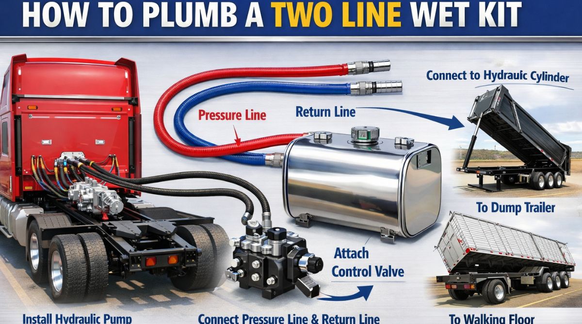
How to plumb a two line wet kit is a common question among truck owners and operators who need hydraulic power for dump trailers, walking floors, live bottoms, or other hydraulic equipment. A two line wet kit is a hydraulic system installed on a truck tractor that supplies pressurized hydraulic fluid to a trailer. It typically consists of a pressure line and a return line, along with a hydraulic pump, reservoir, control valve, and associated fittings and hoses. Proper plumbing of the system is critical to ensure safe operation, long component life, and reliable hydraulic performance.
A two line wet kit differs from a three line system in that it uses one pressure line and one return line between the truck and trailer. In contrast, a three line system adds a dedicated case drain line for certain high-performance applications. Understanding how the two line configuration works is essential before beginning installation.
Understanding the Components of a Two Line Wet Kit
Before plumbing the system, it is important to understand each major component and its function. The hydraulic pump is typically mounted to the truck’s transmission using a power take-off unit. The power take-off transfers mechanical energy from the transmission to drive the pump. The pump then draws hydraulic fluid from the reservoir and sends it under pressure through the system.
The hydraulic reservoir stores the fluid and allows it to cool and de-aerate before recirculation. The control valve regulates fluid flow to the pressure line and directs returning fluid back to the tank. The pressure hose carries high-pressure fluid to the trailer, while the return hose carries used fluid back to the reservoir.
Quick couplers are mounted at the rear of the truck to allow fast connection and disconnection between tractor and trailer. These couplers must be rated for the operating pressure of the system.
Planning the Installation
Proper planning is the first step in how to plumb a two line wet kit. The installer must determine where the hydraulic tank will be mounted, usually on the truck frame rail. Space constraints, exhaust routing, and clearance from suspension components must all be considered.
The pump location depends on the transmission type and the power take-off configuration. Confirm compatibility between the transmission and the PTO unit before installation.
Hose routing must be carefully planned to avoid sharp bends, excessive heat sources, and moving components such as drive shafts or suspension parts. Secure mounting points for clamps and brackets should be identified in advance.
Installing the Hydraulic Reservoir
The reservoir is typically mounted on the side of the truck frame. Use heavy-duty brackets designed to support the weight of the tank when filled with hydraulic fluid. Ensure the mounting hardware is tightened according to manufacturer specifications.
The suction port at the bottom of the tank connects to the inlet of the hydraulic pump. This line must be large enough in diameter to prevent cavitation. Cavitation occurs when the pump does not receive adequate fluid supply, causing air bubbles and potential pump damage.
Install a suction hose rated for hydraulic service. Avoid restrictions in this line, and ensure fittings are properly sealed to prevent air leaks.
Installing the PTO and Hydraulic Pump
After mounting the PTO to the transmission, attach the hydraulic pump securely. The pump inlet connects to the suction line from the reservoir. The outlet of the pump connects to the control valve through a high-pressure hose.
Ensure all fittings are properly torqued. Use thread sealant where recommended, but avoid excessive use that could contaminate the hydraulic system.
Check alignment between the PTO and pump to prevent premature wear. After installation, verify that the PTO engages and disengages smoothly.
Plumbing the Pressure Line
The pressure line carries high-pressure fluid from the control valve to the trailer. This hose must be rated for the maximum operating pressure of the system.
Connect the pump outlet to the inlet port of the control valve. From the valve’s pressure output port, route a hose to the rear of the truck where quick couplers are mounted.
Secure the hose along the truck frame using clamps spaced at regular intervals. Avoid routing near hot exhaust components unless protective heat shielding is used.
At the rear, connect the hose to the pressure-side quick coupler. Labeling the coupler clearly helps prevent incorrect connections.
Plumbing the Return Line
The return line carries fluid back from the trailer to the reservoir. In a two line wet kit, this line is separate from the pressure line and typically enters the tank at a designated return port.
From the rear quick coupler, route the return hose forward along the frame. Connect it to the return port on the control valve or directly to the tank, depending on system design.
Ensure the return line has sufficient diameter to allow unrestricted flow. A restricted return line can cause overheating and increased back pressure.
Install a return line filter if specified by the system manufacturer. This filter removes contaminants before fluid re-enters the tank.
Installing Quick Couplers
Quick couplers are essential for connecting and disconnecting the trailer. Mount them securely to a bracket at the rear of the truck, typically near the frame cross member.
Ensure the pressure and return couplers are clearly marked. Connecting hoses incorrectly can damage hydraulic components.
Check that couplers are compatible with the trailer’s fittings. Standardizing coupler types across equipment reduces confusion and connection issues.
Filling and Priming the System
After plumbing is complete, fill the reservoir with the recommended hydraulic fluid. Consult manufacturer specifications for correct fluid type and viscosity.
Before operating under load, prime the system. Engage the PTO briefly to allow fluid to circulate. Check for leaks at all connections.
Monitor fluid level and add more if necessary. Air trapped in the system may cause temporary noise or jerky operation until fully purged.
Testing the System
Testing is a critical step in how to plumb a two line wet kit. With the trailer connected, engage the PTO and operate the hydraulic equipment slowly.
Observe pressure readings if a gauge is installed. Verify smooth operation and proper function of the control valve.
Check for leaks along hoses and fittings. Even small leaks should be addressed immediately to prevent larger failures.
Monitor fluid temperature during extended operation. Excessive heat may indicate restricted flow or improper hose sizing.
Safety Considerations
Hydraulic systems operate under high pressure and can be dangerous if improperly installed. Always relieve system pressure before disconnecting hoses.
Wear protective gloves and eye protection when working with hydraulic components. High-pressure fluid injection injuries can be severe.
Ensure all hoses are rated for hydraulic service and operating pressure. Never substitute with lower-rated hoses.
Keep hands and clothing away from moving parts when engaging the PTO.
Maintenance After Installation
Regular maintenance ensures long-term reliability. Inspect hoses periodically for signs of wear, cracking, or abrasion.
Check fluid levels routinely and replace filters according to manufacturer recommendations.
Tighten mounting hardware as needed and ensure clamps remain secure.
Keeping the system clean prevents contamination and extends component life.
Common Mistakes to Avoid
One common mistake is using undersized hoses. This restricts flow and increases system heat.
Another mistake is improper hose routing near sharp edges or moving components, leading to premature hose failure.
Failure to properly secure hoses can result in vibration damage.
Incorrectly connecting pressure and return lines at the couplers can cause system malfunction.
Two Line Versus Three Line Systems
Understanding system requirements is important when considering how to plumb a two line wet kit. Two line systems are suitable for many dump and walking floor applications. However, some high-performance hydraulic motors require a dedicated case drain line, which would require a three line setup.
Selecting the correct system configuration ensures compatibility with the intended trailer equipment.
Final Thoughts
Learning how to plumb a two line wet kit requires careful planning, proper component selection, and attention to detail. From mounting the reservoir and pump to routing pressure and return lines, each step plays a critical role in system performance.
By following structured installation procedures, securing hoses properly, verifying connections, and conducting thorough testing, operators can achieve a safe and efficient hydraulic setup. A properly plumbed two line wet kit provides reliable hydraulic power for demanding trailer applications while ensuring durability and long service life.

Introduction to software tgd170.fdm.97 new release
The topic software tgd170.fdm.97 new release refers to a software version or build identifier that is typically associated with system-level applications, firmware updates, or specialized digital tools used in computing environments. In modern software development, versioned releases like this represent updates that may include performance improvements, bug fixes, security enhancements, and feature upgrades.
Software releases are an essential part of the digital ecosystem because they ensure systems remain efficient, secure, and compatible with evolving technologies. A release such as tgd170.fdm.97 would generally indicate a structured versioning system where each segment of the code reflects development stages or internal build tracking.
Within the field of Software Engineering, version control and release cycles are fundamental practices that ensure reliability and continuous improvement of applications.
Understanding software versioning systems
Software versioning is the process of assigning unique identifiers to different stages of software development. These identifiers help developers and users distinguish between older and newer versions of a program.
A version like tgd170.fdm.97 may represent a combination of build series, feature branch, and revision number depending on the internal naming convention used by developers.
Within Computer Science, version control systems are essential tools for managing changes in software over time.
Versioning ensures stability, traceability, and structured development.
Importance of new software releases
New software releases are important because they introduce improvements that enhance functionality, security, and user experience. Each release is typically designed to fix known issues and optimize system performance.
A new release of software like tgd170.fdm.97 may include updates that improve compatibility with hardware or other software systems.
Within Information Technology, software updates are critical for maintaining system efficiency and security.
Regular updates help prevent vulnerabilities and improve usability.
Role of updates in system performance
Software updates often focus on improving system performance by optimizing code, reducing memory usage, and enhancing processing speed. These improvements ensure that applications run more smoothly and efficiently.
A release such as tgd170.fdm.97 new release may include backend optimizations that are not always visible to users but significantly improve performance.
Within Systems Engineering, performance optimization is a key objective in system development.
Efficient systems improve overall user satisfaction.
Security enhancements in software releases
One of the most important aspects of any software update is security enhancement. New releases often patch vulnerabilities that could be exploited by malicious actors.
Software like tgd170.fdm.97 may include security improvements that protect data integrity and system access.
Within Cybersecurity, continuous updates are essential for defending against evolving threats.
Security patches help maintain trust and system safety.
Bug fixes and stability improvements
Bug fixes are a core component of software updates. They address errors, crashes, or unexpected behavior that may occur in previous versions.
A release such as tgd170.fdm.97 new release may resolve known issues to improve system stability.
Within Software Testing, identifying and fixing bugs is a continuous process throughout the development lifecycle.
Stable software ensures reliable user experience.
Feature enhancements in new releases
New software versions often introduce additional features that expand functionality. These features may include improved interfaces, new tools, or better integration with other systems.
A release like tgd170.fdm.97 may include enhancements designed to improve usability and efficiency.
Within Human Computer Interaction, feature design focuses on improving user experience and accessibility.
Better features increase user engagement and productivity.
Compatibility improvements
Software updates also ensure compatibility with newer hardware, operating systems, and third-party applications. This allows users to continue using software without technical conflicts.
The tgd170.fdm.97 new release may include compatibility updates that support newer environments.
Within Systems Integration, compatibility is essential for smooth interaction between different technologies.
Improved compatibility extends software usability.
Role of firmware and system-level updates
Some software versions like tgd170.fdm.97 may be related to firmware or system-level applications. Firmware updates are particularly important because they control hardware behavior at a low level.
These updates improve device performance and fix hardware-related issues.
Within Embedded Systems, firmware plays a critical role in device functionality.
System-level updates ensure hardware and software coordination.
Development lifecycle of software releases
Software development follows a structured lifecycle that includes planning, design, development, testing, deployment, and maintenance. Each release represents a stage in this continuous cycle.
A version like tgd170.fdm.97 new release is part of this iterative improvement process.
Within Software Development Lifecycle, iterative updates ensure long-term software quality.
Each release improves upon the previous version.
Importance of testing before release
Before a software update is released, it undergoes extensive testing to ensure reliability and stability. This includes unit testing, integration testing, and system testing.
The goal is to identify and fix issues before public deployment.
Within Quality Assurance, testing is essential for maintaining software standards.
Proper testing reduces post-release errors.
User experience improvements
Software updates often focus on enhancing user experience by improving interface design, responsiveness, and usability.
A new release like tgd170.fdm.97 may include interface refinements that make the system easier to use.
Within User Experience Design, usability is a key factor in software success.
Better design increases user satisfaction.
Role of documentation in software releases
Documentation is an important part of any software release. It helps users and developers understand new features, changes, and technical requirements.
A release such as tgd170.fdm.97 new release would typically be accompanied by technical notes and update descriptions.
Within Technical Writing, clear documentation improves usability and understanding.
Well-documented software is easier to maintain.
Importance of backward compatibility
Backward compatibility ensures that new software versions work with older systems or data formats. This is important for users who may not immediately upgrade their entire system.
A release like tgd170.fdm.97 may maintain compatibility with previous versions.
Within Computer Architecture, compatibility is essential for system continuity.
It prevents disruption during upgrades.
Role of automation in software updates
Modern software systems often use automated processes for updates and deployment. This reduces manual effort and ensures faster delivery of improvements.
The release process for software like tgd170.fdm.97 may involve automated pipelines.
Within DevOps, automation improves efficiency and reliability.
Automation speeds up software delivery.
Future of software release systems
Software release systems are evolving toward more frequent updates, cloud-based deployment, and real-time improvements. This ensures continuous enhancement of applications.
Future versions of systems like tgd170.fdm.97 may become more adaptive and intelligent.
Within Artificial Intelligence, intelligent automation is shaping the future of software development.
Software is becoming more dynamic and responsive.
Conclusion
The software tgd170.fdm.97 new release represents a structured update within a software development lifecycle focused on improving performance, security, and functionality. Within the framework of Software Engineering, such releases are essential for maintaining system reliability and continuous improvement.
Software updates ensure that digital systems remain efficient, secure, and compatible with evolving technological environments, making them a critical part of modern computing infrastructure.

An AGV Automated Guided Vehicle is a highly advanced material handling system designed to transport goods within industrial environments without direct human intervention. These vehicles are widely used in warehouses, manufacturing facilities, and distribution centers, where efficiency, accuracy, and automation are essential. AGVs represent a major development in the field of Industrial Automation, combining mechanical systems, sensors, and intelligent control to perform tasks that were traditionally handled manually.
The concept of automated guided vehicles is rooted in the need to improve productivity and reduce operational costs. As industries continue to adopt automation, AGVs have become an integral part of modern logistics and manufacturing systems. Their ability to operate continuously and adapt to changing conditions makes them a valuable asset in complex operational environments.
History and Evolution of AGV Systems
The development of AGV Automated Guided Vehicle technology dates back to the mid-twentieth century, when early versions were introduced to simplify material transport in factories. These initial systems relied on fixed paths, such as wires embedded in the floor, to guide the vehicles.
Over time, advancements in technology have significantly enhanced the capabilities of AGVs. Modern systems incorporate sensors, cameras, and sophisticated software to navigate environments more flexibly. This evolution has transformed AGVs from simple transport tools into intelligent systems capable of complex decision-making.
The integration of technologies from Robotics and Artificial Intelligence has further expanded the functionality of AGVs, enabling them to operate in dynamic and unpredictable environments.
Types of AGV Automated Guided Vehicle Systems
AGV systems are available in various types, each designed to meet specific operational needs. One common type is the tow vehicle, which is used to pull carts or trailers. These vehicles are often used in manufacturing environments where materials need to be moved between different workstations.
Unit load carriers are another type, designed to transport individual loads such as pallets or containers. These vehicles are commonly used in warehouses and distribution centers.
Forklift AGVs replicate the functionality of traditional forklifts but operate autonomously. They are capable of lifting and transporting heavy loads, making them suitable for industrial applications.
Assembly line AGVs are used to move products through different stages of production. These vehicles ensure a smooth and continuous workflow, improving efficiency and reducing downtime.
Navigation Technologies
One of the defining features of an AGV Automated Guided Vehicle is its navigation system. Early AGVs relied on fixed paths, but modern systems use advanced navigation technologies to operate more flexibly.
Laser guidance is a common method, where the vehicle uses lasers to detect reflectors placed in the environment. This allows for precise positioning and movement.
Magnetic tape and markers are also used in some systems, providing a predefined path for the vehicle to follow. While less flexible, this method is reliable and cost-effective.
Vision-based navigation uses cameras and image processing to identify landmarks and navigate the environment. This approach allows AGVs to operate in more complex and dynamic settings.
Another advanced method is simultaneous localization and mapping, where the vehicle creates a map of its surroundings and uses it to navigate in real time.
Components of AGV Systems
An AGV Automated Guided Vehicle consists of several key components that work together to enable autonomous operation. The control system is the central component, responsible for processing data and making decisions.
Sensors play a crucial role in detecting obstacles and ensuring safe operation. These may include proximity sensors, cameras, and laser scanners.
The drive system enables movement, while the power system provides the energy needed for operation. Batteries are commonly used, and advancements in battery technology have improved the efficiency and runtime of AGVs.
Communication systems allow AGVs to interact with other vehicles and central control systems. This coordination is essential for optimizing operations and preventing collisions.
Applications in Industry
AGV Automated Guided Vehicle systems are used across a wide range of industries. In manufacturing, they are used to transport raw materials, components, and finished products between different stages of production.
In warehousing and logistics, AGVs handle tasks such as picking, packing, and transporting goods. Their ability to operate continuously makes them ideal for high-demand environments.
The automotive industry is one of the largest users of AGVs, where they are used to support assembly lines and manage inventory. Other industries, such as food and beverage, pharmaceuticals, and electronics, also benefit from AGV technology.
Benefits of AGV Automated Guided Vehicle Systems
The adoption of AGV Automated Guided Vehicle systems offers numerous benefits. One of the most significant advantages is increased efficiency. AGVs can operate continuously without breaks, ensuring consistent productivity.
Another benefit is improved accuracy. Automated systems reduce the likelihood of human error, leading to more reliable operations.
Safety is also enhanced, as AGVs are equipped with sensors and control systems that prevent collisions and ensure safe operation. This reduces the risk of workplace accidents.
Cost savings is another important advantage. While the initial investment may be significant, the long-term benefits of reduced labor costs and increased efficiency often outweigh the costs.
Challenges and Limitations
Despite their advantages, AGV systems also face certain challenges. One of the main issues is the initial cost of implementation. Setting up an AGV system requires investment in equipment, infrastructure, and training.
Another challenge is the complexity of integration. AGVs must be integrated with existing systems and processes, which can be difficult in some environments.
Maintenance and reliability are also important considerations. While AGVs are designed to be durable, they require regular maintenance to ensure optimal performance.
Flexibility can be a limitation in some systems, particularly those that rely on fixed paths. However, advancements in navigation technology are addressing this issue.
Role in Modern Automation
AGV Automated Guided Vehicle systems play a crucial role in modern automation. They are a key component of smart factories and automated warehouses, where efficiency and precision are essential.
The integration of AGVs with other technologies, such as robotics and data analytics, creates a more connected and intelligent system. This integration supports real-time decision-making and improves overall performance.
As industries continue to embrace automation, the importance of AGVs is expected to grow, making them a fundamental part of future industrial systems.
Future Trends and Innovations
The future of AGV Automated Guided Vehicle technology is shaped by ongoing advancements in technology. One major trend is the development of more intelligent systems that can adapt to changing conditions.
The use of artificial intelligence is expected to enhance decision-making capabilities, allowing AGVs to operate more autonomously. Improvements in battery technology will also increase efficiency and reduce downtime.
Another trend is the integration of AGVs with the Internet of Things, enabling better communication and coordination between devices. This connectivity will create more efficient and responsive systems.
Collaborative robots, or cobots, are also being integrated with AGVs, creating hybrid systems that combine mobility and manipulation capabilities.
Impact on Workforce and Operations
The introduction of AGV Automated Guided Vehicle systems has a significant impact on the workforce and operations. While automation reduces the need for manual labor in certain tasks, it also creates new opportunities in areas such as system management and maintenance.
Employees can focus on more complex and value-added activities, improving overall productivity. Training and skill development are essential to ensure that the workforce can adapt to these changes.
From an operational perspective, AGVs improve efficiency, reduce errors, and enhance flexibility. These benefits contribute to the overall success of organizations.
Conclusion
AGV Automated Guided Vehicle systems represent a major advancement in the field of Industrial Automation, offering a powerful solution for modern material handling and logistics challenges. By combining technologies from Robotics and Artificial Intelligence, AGVs provide a level of efficiency and precision that is difficult to achieve with manual methods.
From their history and types to their applications and future trends, AGVs have become an essential part of industrial operations. Despite challenges, their benefits in terms of efficiency, safety, and cost savings make them a valuable investment for organizations.
As technology continues to evolve, AGV Automated Guided Vehicle systems will play an increasingly important role in shaping the future of automation, supporting innovation and driving progress across industries.

The Federal Bureau of Investigation (FBI) plays a critical role in national security, law enforcement, and cyber intelligence. While most people associate the FBI with criminal investigations and counterterrorism, the agency also has a strong connection to software development. This connection is multifaceted, involving cybersecurity, investigative tools, internal software, partnerships with private software companies, and research into emerging technologies. Understanding how the FBI is connected with soft software development requires an in-depth look at the agency’s objectives, the types of software it develops and uses, its collaborations with the technology sector, and the implications for security and law enforcement.
the role of software in the fbi
Software is essential to the FBI’s daily operations. From managing case files to conducting cyber investigations, software allows agents and analysts to collect, analyze, and secure information efficiently. Software in the FBI can be categorized into three broad areas: investigative tools, internal management systems, and cybersecurity technologies.
investigative software
Investigative software enables the FBI to analyze large datasets, track criminal networks, and uncover patterns. Tools in this category include databases for criminal records, forensic software for analyzing digital evidence, and intelligence software that monitors communications for security threats. These programs often require sophisticated algorithms and secure coding practices to handle sensitive data without exposing it to external threats.
internal management software
The FBI uses software to manage internal processes such as personnel management, document workflow, scheduling, and financial operations. Internal management systems are often custom-developed or adapted from commercial software, ensuring compliance with federal security regulations while optimizing operational efficiency.
cybersecurity and threat detection
Cybersecurity is a major concern for the FBI. The agency develops and deploys software to detect, prevent, and respond to cyberattacks. This includes intrusion detection systems, malware analysis tools, network monitoring software, and threat intelligence platforms. By creating specialized software, the FBI can anticipate emerging threats, secure critical infrastructure, and assist other government agencies and private organizations in preventing cybercrime.
collaboration with private software developers
The FBI frequently collaborates with private software companies and open-source communities. These partnerships allow the agency to leverage advanced technologies, adapt commercial software for government use, and ensure compliance with evolving cybersecurity standards. Collaborations also include joint research projects, software testing programs, and technology transfer initiatives that bring innovative tools from the private sector into law enforcement applications.
software acquisition programs
The FBI acquires software through federal procurement programs, often customizing it to meet unique operational requirements. These programs include Request for Proposals (RFPs) from tech vendors, internal development projects, and collaboration with academic institutions. By integrating external expertise, the FBI can maintain cutting-edge tools while managing costs and ensuring secure implementation.
innovation and research partnerships
The FBI engages in research partnerships with universities and technology incubators to explore emerging technologies such as artificial intelligence, machine learning, and predictive analytics. These technologies enhance investigative software by automating data analysis, identifying patterns in criminal activity, and improving predictive models for law enforcement strategies.
software development within the fbi
While the FBI works with external software vendors, it also develops proprietary software internally. This internal development focuses on highly sensitive tools that must meet strict security standards. FBI software developers often follow agile methodologies, emphasizing rapid iteration, testing, and secure coding practices.
secure coding practices
Given the sensitive nature of FBI operations, secure coding practices are a top priority. Developers must follow federal security guidelines, including encryption standards, access controls, and audit trails. Software undergoes rigorous testing to prevent vulnerabilities that could compromise investigations or expose classified information.
agile and iterative development
The FBI often uses agile development methodologies to adapt to rapidly changing investigative needs. Software projects are divided into iterative cycles, allowing developers to respond quickly to operational feedback, update features, and address security concerns promptly.
the impact of cybersecurity initiatives
The FBI’s connection to software development is particularly evident in its cybersecurity initiatives. The agency has developed specialized software for monitoring networks, tracking cybercriminal activity, and analyzing malware. These tools allow the FBI to investigate high-profile cybercrimes, assist other government agencies, and support private companies in defending against threats.
malware analysis and threat intelligence
FBI software tools for malware analysis and threat intelligence provide detailed insights into cyberattacks. These programs can dissect malicious code, identify attackers’ tactics, and recommend countermeasures. This capability is critical for preventing data breaches, ransomware attacks, and other cybercrimes.
incident response and digital forensics
Software plays a central role in digital forensics, enabling the FBI to recover and analyze electronic evidence. Tools developed or customized by the agency help extract data from devices, trace cyber intrusions, and maintain the integrity of digital evidence for use in court. Efficient software ensures that evidence collection is accurate, legally compliant, and reproducible.
training and workforce development
To effectively use and develop software, the FBI invests heavily in training its workforce. Agents and analysts receive instruction in software applications, cybersecurity practices, and digital forensics. Additionally, the FBI employs software engineers and data scientists who are trained in secure software development and investigative technologies.
specialized training programs
FBI training programs cover a wide range of software-related skills, including network analysis, programming languages, data analytics, and threat detection. These programs ensure that personnel can effectively utilize software tools in investigations, maintain system security, and contribute to internal development projects.
continuous professional development
Due to the rapidly evolving technology landscape, the FBI emphasizes continuous professional development. Personnel are encouraged to stay updated on software trends, cybersecurity threats, and emerging technologies to maintain the agency’s operational effectiveness.
legal and ethical considerations
The FBI’s involvement in software development also raises legal and ethical considerations. Developing investigative tools requires careful attention to privacy laws, data protection regulations, and ethical standards. Software must balance effective law enforcement capabilities with the protection of civil liberties.
privacy and data protection
FBI software systems must comply with laws governing the collection, storage, and use of personal data. Encryption, access controls, and auditing are essential to prevent unauthorized access and ensure accountability.
ethical software development
Ethical considerations guide the development of investigative software. Developers must ensure that tools are used responsibly, do not target individuals unfairly, and are transparent in their operations to the extent permitted by law.
conclusion
The connection between the FBI and software development is extensive and multifaceted. The agency relies on software for investigations, internal management, cybersecurity, and digital forensics. Collaboration with private software developers, internal development projects, and research partnerships ensures that the FBI maintains cutting-edge tools while adhering to strict security and ethical standards. Training and workforce development further strengthen the agency’s capabilities, ensuring personnel can effectively use and develop software for national security and law enforcement purposes. By combining technology, expertise, and ethical considerations, the FBI exemplifies how software development can support complex investigative and security objectives in a modern, technology-driven world.

4029339118: Complete Guide, Meaning, Purpose, and Important Information

2566966212: Complete Guide, Identification, Uses, and Important Details

4023164651: Meaning, Details, and Complete Information Explained
