
Automotive
How to Repair Code U110B on a 09 Mercedes E350

The 09 Mercedes E350 is a luxury sedan renowned for its engineering, performance, and advanced electronics. Like many modern vehicles, the 2009 E350 relies on a complex network of electronic control modules and sensors that communicate via a Controller Area Network (CAN bus). When a fault occurs in this communication system, diagnostic trouble codes (DTCs) such as U110B are generated. The U110B code specifically relates to a “Lost Communication with Transmission Control Module” or similar network communication error. Repairing this code involves understanding the underlying systems, identifying the cause, and taking a structured approach to restore normal communication between modules. This guide provides a comprehensive, step-by-step explanation of how to repair code U110B on a 09 Mercedes E350, along with diagnostic tips, tools required, and preventative maintenance practices.
Understanding Code U110B
Code U110B is a network-related diagnostic trouble code that indicates a disruption in communication between the transmission control module (TCM) and other electronic modules in the vehicle, such as the engine control module (ECM) or ABS module. The TCM controls transmission functions, gear shifts, and torque management. When communication is interrupted, the vehicle may experience erratic shifting, warning lights on the dashboard, reduced performance, or limp mode activation. Understanding that U110B is not necessarily a mechanical transmission fault but a communication issue is key to addressing it effectively.
Common Causes of U110B on a 09 Mercedes E350
Several factors can trigger the U110B code in a 2009 Mercedes E350. Common causes include:
- Loose or corroded electrical connections at the transmission, ECM, or CAN bus connectors.
- Damaged or frayed wiring in the transmission harness or network lines.
- Faulty Transmission Control Module (TCM) causing intermittent communication failures.
- Low or contaminated transmission fluid, which can cause the TCM to malfunction.
- Battery voltage issues or weak power supply affecting module operation.
- Faulty ground connections, leading to intermittent communication errors.
- Software or firmware issues, sometimes resolved through module updates.
Identifying the root cause requires a systematic approach, as misdiagnosis can lead to unnecessary replacement of expensive components.
Tools and Equipment Needed
Repairing U110B requires diagnostic tools and basic mechanical tools. Essential equipment includes:
- OBD-II scanner capable of reading Mercedes-specific codes and module communication faults.
- Multimeter for testing voltage, continuity, and resistance in electrical circuits.
- Socket and wrench set for accessing the transmission and related modules.
- Screwdrivers and pliers for connectors and clips.
- Battery charger or stabilized power supply, if testing under controlled voltage conditions.
- Basic hand tools to remove panels and covers for module access.
Having these tools ensures accurate diagnosis and safe repair procedures without damaging sensitive electronic components.
Preparing the Vehicle
Before starting any diagnostic or repair work, ensure safety and proper preparation. Park the Mercedes E350 on a flat surface, engage the parking brake, and disconnect the negative battery terminal to prevent short circuits. Wait for at least 10-15 minutes to allow modules to enter sleep mode before inspecting wiring or connectors. Proper preparation avoids accidental damage to modules, preserves electronic memory, and reduces the risk of personal injury.
Initial Diagnostic Scan
The first step in addressing code U110B is performing a full diagnostic scan using an OBD-II scanner with Mercedes-Benz capabilities. Connect the scanner to the OBD-II port, retrieve the stored DTCs, and note any related codes. Check live data for the transmission control module to see if it responds to the scan tool. This initial scan helps determine whether the communication issue is persistent, intermittent, or associated with other systems. Reviewing freeze-frame data may provide additional insight into the conditions under which the code occurred.
Inspecting Electrical Connections
Many U110B codes are caused by loose, corroded, or damaged connections. Inspect the wiring harness at the TCM, ECM, and relevant CAN bus connectors. Look for corrosion, bent pins, or broken wires. Clean corroded terminals using an appropriate contact cleaner and a small brush. Secure loose connectors and ensure that clips are fully engaged. Repair damaged wiring using solder and heat shrink tubing to restore continuity. Proper electrical connection is critical for reliable communication between modules.
Checking Transmission Grounds and Power Supply
Faulty grounds or unstable power supply can trigger communication errors. Verify that the transmission ground strap is secure and free of corrosion. Use a multimeter to check voltage at the TCM power input and ground terminals. Voltage should remain within manufacturer-specified ranges, typically around 12 volts with the engine off and slightly higher when running. Correct any loose ground or voltage issues, as unstable power can cause intermittent communication errors, including U110B.
Inspecting Transmission Fluid
Transmission fluid levels and quality can impact TCM performance. Low or contaminated fluid may cause the module to operate incorrectly or lose communication. Check the transmission fluid level and inspect its color and smell. If fluid is dark, burnt, or contaminated, perform a complete transmission fluid change following Mercedes specifications. Proper fluid maintenance supports TCM operation and can resolve certain U110B codes without replacing electronic components.
Software Updates and Module Reset
Sometimes, communication errors can result from outdated TCM firmware or software glitches. Consult a Mercedes-Benz dealer or certified workshop for available software updates for the TCM and ECM. In many cases, performing a module reset using a professional scan tool can clear intermittent errors. To reset, reconnect the battery, clear all stored codes, and allow the vehicle to complete a drive cycle to see if the code returns. Updating software and resetting modules can resolve bugs that cause false U110B detections.
Testing CAN Bus Communication
If the code persists, perform a CAN bus network test. Using a multimeter or diagnostic oscilloscope, check for proper voltage levels and signal continuity on CAN High and CAN Low lines between the TCM and ECM. Look for shorts to ground, short to power, or open circuits that may disrupt module communication. Repair or replace any faulty wiring identified during testing. Proper CAN bus function is essential for all networked modules in the Mercedes E350, not just the transmission.
Replacing Faulty Modules
If diagnostics confirm that the TCM is defective, replacement may be required. Remove the faulty TCM following manufacturer guidelines, taking care to disconnect all connectors properly. Install the new module, secure it in place, and reconnect wiring harnesses. After installation, perform a module programming or adaptation procedure using a Mercedes-certified scan tool. This ensures that the new TCM communicates correctly with the ECM and other modules. Replacement should be considered a last resort after all wiring, fluid, and software issues are ruled out.
Verifying Repair
After addressing the identified cause, perform a full system scan and test drive the vehicle to confirm the repair. Monitor live data for the transmission and other related modules, ensuring normal operation and smooth shifting. Check that the U110B code no longer appears and that no new codes have been generated. Multiple drive cycles may be necessary to verify that the issue is resolved under various operating conditions.
Preventative Maintenance and Tips
Preventing future U110B codes involves proper vehicle maintenance and careful attention to electronics. Regularly inspect wiring harnesses, connectors, and grounds for corrosion or wear. Maintain transmission fluid at recommended levels and replace it at appropriate intervals. Keep the battery fully charged and avoid voltage drops that may affect module communication. Avoid aftermarket modifications that interfere with the CAN bus network. Following preventative measures reduces the likelihood of network communication errors and prolongs the life of the Mercedes E350’s electronic systems.
Common Mistakes to Avoid
When repairing U110B, avoid common mistakes such as replacing the TCM without performing a thorough wiring and power inspection, neglecting software updates, or ignoring transmission fluid condition. Rushing the repair without proper diagnostics can result in recurring codes and unnecessary expenses. Always follow structured diagnostic procedures, use quality tools, and adhere to manufacturer specifications for safe and effective repair.
Conclusion
Repairing code U110B on a 09 Mercedes E350 requires a systematic approach involving accurate diagnosis, inspection of electrical connections, verification of power and grounds, transmission fluid assessment, software updates, CAN bus testing, and, if necessary, module replacement. Understanding that U110B indicates a communication issue rather than a mechanical transmission failure is crucial for targeting the correct repair. By following the steps outlined in this guide, vehicle owners can restore proper transmission module communication, resolve erratic shifting issues, and maintain the safety and performance of their Mercedes E350. Regular maintenance, careful inspection, and timely software updates prevent future occurrences and ensure the vehicle operates reliably and efficiently.

If you are searching for how to remove cls450 front bumper cover forum discussions, you are likely looking for detailed, practical guidance from owners and enthusiasts who have already performed the job. The CLS450 is part of the luxury CLS lineup from Mercedes-Benz, and while it offers refined styling and advanced technology, even premium vehicles occasionally require maintenance, repairs, or cosmetic upgrades. Removing the front bumper cover may be necessary for tasks such as replacing a damaged grille, installing a new sensor, repairing impact damage, upgrading lighting components, or repainting the bumper.
The Mercedes-Benz CLS450 features a modern front fascia design with integrated sensors, parking assistance systems, and sleek LED lighting. Because of this complexity, removing the bumper cover requires patience, the correct tools, and an understanding of how the components are assembled. Many forum users emphasize taking your time and documenting each step with photos to ensure smooth reinstallation.
Understanding the CLS450 Front Bumper Structure
Before starting the removal process, it is important to understand how the bumper is constructed. The CLS450 front bumper consists of a plastic outer cover attached to a reinforced internal structure. The cover is secured with screws, bolts, plastic clips, and fasteners along the top, bottom, and inside the wheel wells.
Modern models often include integrated components such as parking sensors, radar units for driver assistance systems, air intake ducts, and fog light housings. Disconnecting these properly is essential to prevent damage.
Forum discussions frequently highlight that the bumper cover is not extremely heavy, but it is wide and somewhat flexible. Having a second person assist during removal helps avoid bending or scratching the painted surface.
Tools Required for the Job
When reviewing how to remove cls450 front bumper cover forum advice, most users recommend gathering the proper tools before beginning. Typically, you will need a socket wrench set with metric sockets, a Torx bit set, plastic trim removal tools, a flathead screwdriver, and possibly a Phillips screwdriver. A trim clip removal tool is especially helpful to avoid breaking plastic fasteners.
It is also recommended to have a soft blanket or foam pad ready to place the bumper cover on once removed. This prevents paint scratches or scuffs.
Safety gloves are useful to protect your hands from sharp plastic edges or metal brackets. Good lighting is important as well, especially when working inside the wheel arches.
Preparing the Vehicle
Preparation is a crucial step. Park the vehicle on a flat surface and engage the parking brake. Turning the steering wheel fully to one side provides better access to the wheel well fasteners. Some forum members suggest removing the front wheels entirely for maximum space, though this is optional.
Disconnecting the battery may be advisable if you will be unplugging electronic sensors or radar modules. This reduces the risk of triggering warning lights or short circuits.
Opening the hood allows access to the upper mounting points of the bumper cover. These are typically located along the radiator support area.
Removing the Upper Fasteners
Under the hood, you will find several screws or bolts securing the top edge of the bumper to the front support structure. Carefully remove these using the appropriate socket or Torx bit.
Forum users often recommend placing all removed hardware in labeled containers to keep track of different screw lengths and types. Losing or mixing up fasteners can complicate reinstallation.
Once the upper bolts are removed, the bumper cover will still be secured at the sides and bottom.
Detaching Wheel Well Fasteners
Next, focus on the wheel wells. Inside each front wheel arch, there are multiple screws and plastic clips attaching the bumper cover to the fender liner.
Using a trim removal tool helps avoid damaging the clips. Gently pull back the fender liner to expose hidden screws securing the side edges of the bumper.
Many forum contributors note that this area can be tight, so patience is essential. Avoid pulling forcefully, as the painted tabs connecting the bumper to the fender can break if stressed.
Removing Lower Screws and Splash Shield Connections
Underneath the vehicle, the bumper cover connects to the lower splash shield and undertray. Remove the screws or bolts securing these sections.
In some models, additional fasteners are positioned near the front lip or air dam. Carefully inspect the entire lower edge before attempting to pull the bumper away.
Failing to remove a hidden fastener can result in cracked plastic tabs.
Disconnecting Electrical Components
One of the most important steps mentioned in how to remove cls450 front bumper cover forum threads is properly disconnecting electrical connectors. The CLS450 often includes front parking sensors, a front camera, radar sensors for adaptive cruise control, and LED daytime running lights.
Once the bumper is partially loosened, gently pull it forward a few inches and reach behind to unplug connectors. Press the release tabs carefully and avoid yanking wires.
Labeling connectors with tape can help during reinstallation, especially if multiple plugs look similar.
Removing the Bumper Cover
With all fasteners removed and connectors unplugged, the bumper cover can be detached. This step is best done with assistance. Each person should hold one side and gently pull outward at the corners near the fenders to release the side clips.
After releasing the sides, carefully pull the bumper forward and away from the vehicle. Place it on a prepared soft surface to prevent damage.
Forum members frequently emphasize checking once more for any missed connectors or clips before fully separating the bumper.
Common Challenges and Troubleshooting
Some users report difficulty with stubborn clips near the headlights. Applying gentle outward pressure while lifting slightly can help release these tabs.
Another common issue involves broken plastic retaining clips. Replacement clips are relatively inexpensive and should be replaced if damaged to ensure secure reinstallation.
If warning lights appear after reinstallation, they may be related to improperly connected sensors. Double-check all electrical connections before assuming a more serious issue.
Reinstallation Tips
Reinstalling the bumper cover follows the reverse order of removal. Position the bumper carefully and reconnect all electrical connectors before fully securing it.
Align the side tabs with the fender slots and press firmly until they click into place. Install lower screws and splash shield fasteners first to support the bumper’s weight.
Next, secure the wheel well screws and clips, ensuring the fender liner is properly aligned. Finally, tighten the upper bolts under the hood.
Do not overtighten screws, as this can strip plastic mounting points.
When to Seek Professional Help
Although many enthusiasts successfully remove the bumper themselves, some situations warrant professional assistance. If your vehicle is equipped with advanced driver assistance systems requiring sensor recalibration, a certified technician may be necessary.
Complex radar units integrated into the front fascia sometimes require precise alignment after removal. Incorrect positioning can affect adaptive cruise or collision prevention systems.
Additionally, if the bumper removal is related to accident damage, hidden structural components may need inspection.
Importance of Forum-Based Knowledge
The phrase how to remove cls450 front bumper cover forum reflects the value of community knowledge. Owners who share firsthand experiences provide practical insights beyond official service manuals.
Forums often include photos, step-by-step walkthroughs, and troubleshooting tips that simplify complex procedures. Reading multiple threads before beginning can prepare you for unexpected challenges.
While official repair manuals from Mercedes-Benz offer precise specifications, community advice adds real-world perspective.
Safety Considerations
Always work in a well-lit, stable environment. Avoid rushing the process. Keep hardware organized and protect painted surfaces from scratches.
If lifting the vehicle for better access, use proper jack stands rather than relying solely on a hydraulic jack.
Take extra care with delicate components such as sensors and wiring harnesses.
Final Thoughts
Searching how to remove cls450 front bumper cover forum typically means you want a practical, experience-based explanation rather than a brief overview. Removing the front bumper cover on the Mercedes-Benz CLS450 is a manageable task for those with moderate mechanical skill and patience.
Understanding the bumper’s attachment points, carefully removing fasteners, disconnecting electronic components properly, and working methodically are key to success. With preparation and attention to detail, the process can be completed safely and efficiently.
Whether your goal is repair, customization, or maintenance, following structured guidance ensures that your CLS450 remains in excellent condition while avoiding unnecessary damage or complications.
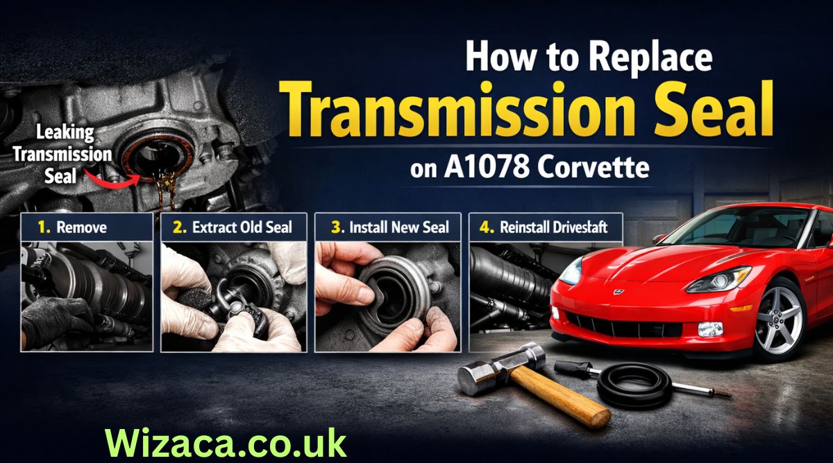
The A1078 Corvette is an iconic sports car known for its performance, precision engineering, and high reliability. One important maintenance task that ensures smooth performance and prevents leaks is replacing the transmission seal. The transmission seal plays a critical role in maintaining fluid integrity within the transmission, preventing leaks that could lead to transmission damage or failure. Over time, seals can degrade due to heat, pressure, and wear, making replacement necessary to maintain optimal performance. how to replace the transmission seal on an A1078 Corvette, along with tools required, safety considerations, troubleshooting, and maintenance tips.
Understanding the Transmission Seal
Transmission seals are rubber or synthetic components designed to prevent fluid leaks where the transmission interfaces with other parts, such as the engine, driveshaft, or valve body. In the A1078 Corvette, the most common seal that requires replacement is the input or output shaft seal, often referred to as the rear main seal for the transmission. These seals are subjected to constant pressure, high temperatures, and rotational forces. A worn or damaged seal can result in transmission fluid leaks, low fluid levels, increased wear on transmission components, and eventually, costly repairs if not addressed promptly. Understanding the purpose and location of the seal is critical for proper replacement.
Signs of a Failing Transmission Seal
Before proceeding with replacement, it is important to recognize the symptoms of a failing transmission seal. Common signs include visible fluid leaks beneath the vehicle, transmission fluid stains on the driveway, a low transmission fluid level despite regular topping off, unusual noises from the transmission, or difficulty shifting gears. Timely replacement of the seal at the first signs of leakage prevents further damage to the transmission and ensures the vehicle continues to operate efficiently. Ignoring a worn seal can lead to overheating, increased friction, and permanent damage to transmission components.
Tools and Materials Required
Replacing the transmission seal on an A1078 Corvette requires careful preparation and the correct tools. Essential tools include a floor jack, jack stands, socket set, wrench set, screwdrivers, seal puller, and a seal installation tool or driver. Additionally, you will need a replacement transmission seal specifically designed for the A1078 Corvette, high-quality transmission fluid, and rags or towels for cleaning. Having the proper tools and materials ensures that the replacement process is safe, efficient, and precise, reducing the risk of damage to the transmission or surrounding components.
Preparing the Vehicle for Maintenance
Safety is paramount when performing any transmission maintenance. Begin by parking the Corvette on a level surface and engaging the parking brake. Wear protective gloves and safety glasses to prevent injury from transmission fluid or debris. Lift the vehicle using a floor jack and support it securely on jack stands, ensuring it is stable before working underneath. Remove the transmission cover or splash guard if present to access the transmission pan and seal area. Proper preparation minimizes the risk of injury and ensures that the replacement process can be carried out smoothly.
Draining Transmission Fluid
Before removing the transmission seal, it is necessary to drain the transmission fluid. Place a drain pan beneath the transmission pan and remove the drain plug, allowing fluid to flow out completely. If the transmission does not have a drain plug, the pan may need to be removed carefully to prevent spillage. Draining the fluid reduces mess during seal removal and prevents contamination of the new seal. Inspect the fluid for metal shavings or discoloration, which may indicate additional transmission wear that needs attention. Replacing the fluid with high-quality transmission fluid after the seal installation is essential for optimal performance.
Removing the Transmission Pan
After draining the fluid, the next step is to remove the transmission pan if necessary. Use a socket set to loosen and remove the bolts securing the pan to the transmission. Carefully lower the pan and clean it thoroughly, removing any gasket material or debris. Removing the pan provides clear access to the transmission seal and internal components. Be cautious to avoid damaging the pan or gasket surface, as a proper seal is necessary to prevent leaks after reassembly. Inspect the pan for signs of wear, rust, or damage, and replace it if necessary.
Accessing the Transmission Seal
With the pan removed, the transmission seal is usually accessible at the input or output shaft, depending on the specific configuration of the A1078 Corvette. In some cases, the driveshaft may need to be disconnected to access the seal fully. Use appropriate tools to remove the driveshaft or related components carefully. Take note of the orientation and positioning of all parts removed, as this will assist in reassembly. Documenting the process or taking photos can help ensure that reinstallation is accurate and prevents mistakes that could cause leaks or misalignment.
Removing the Old Transmission Seal
Removing the old transmission seal requires care to avoid damaging the transmission housing or shaft. Use a seal puller or a flathead screwdriver to gently pry the seal out of its seating. Be careful not to scratch the shaft or housing, as imperfections can prevent the new seal from seating properly. Clean the area thoroughly with a rag and a suitable cleaner to remove any residual fluid, dirt, or debris. Inspect the shaft for wear, scoring, or damage, which could compromise the new seal. If the shaft is damaged, consider consulting a professional or replacing the affected component before installing the new seal.
Installing the New Transmission Seal
Proper installation of the new transmission seal is critical for preventing leaks. Apply a thin layer of clean transmission fluid or appropriate lubricant to the seal’s inner edge to facilitate smooth installation. Position the seal carefully over the shaft and press it evenly into its seating. Use a seal installation tool or a socket of appropriate diameter to gently tap the seal into place, ensuring it is flush with the housing. Avoid striking the seal too hard or at an angle, as this can deform the seal and compromise its effectiveness. Proper installation ensures a long-lasting seal that prevents fluid leaks and maintains transmission integrity.
Reassembling Components
After the seal is installed, reassemble any components removed during the process. Reattach the driveshaft or related parts, ensuring proper alignment and secure fastening. Reinstall the transmission pan with a new gasket if required, tightening the bolts to the manufacturer’s torque specifications. Ensure that all connections are secure and that no components are pinched or misaligned. Correct reassembly prevents leaks, rattling, or transmission damage during operation. Double-check all components and fasteners before proceeding to refill the transmission fluid.
Refilling Transmission Fluid
Once the transmission seal and pan are properly installed, refill the transmission with the recommended type and quantity of transmission fluid for the A1078 Corvette. Use a funnel to prevent spillage and check the fluid level using the transmission dipstick while the engine is running. Proper fluid level ensures smooth shifting, lubrication of internal components, and cooling of the transmission. Overfilling or underfilling can cause performance issues or damage, so follow the manufacturer’s guidelines closely. Regularly checking the fluid level after replacement helps confirm that the seal is functioning correctly and that there are no leaks.
Testing and Verification
After completing the replacement and refilling the transmission fluid, it is important to test the vehicle. Start the engine and allow it to reach operating temperature. Shift through all gears and observe for smooth engagement, unusual noises, or fluid leaks. Inspect the area around the new seal and transmission pan for signs of leakage. A proper test ensures that the seal has been installed correctly and that the transmission is operating efficiently. Monitoring the vehicle over the next few days can help identify any issues early and confirm the success of the replacement.
Common Issues and Troubleshooting
Even after proper installation, some issues may arise. If there are leaks, check that the seal is seated correctly and that the pan gasket is intact. Inspect the torque on bolts and ensure all components were reinstalled in the correct order. Air trapped in the transmission system can sometimes cause irregular fluid levels; running the vehicle through gear cycles helps release trapped air. If persistent issues occur, consult a professional mechanic for further inspection. Regular monitoring and maintenance prevent long-term transmission damage and ensure consistent performance.
Maintenance Tips for Transmission Seals
Maintaining the transmission seal involves routine inspections and proper fluid management. Check the transmission fluid level and condition regularly, and replace it according to the manufacturer’s recommended intervals. Avoid harsh driving conditions that can increase heat and pressure in the transmission, as this accelerates seal wear. Keeping the transmission clean and free from contaminants prolongs the life of the seal. Addressing minor leaks early prevents larger problems and extends the overall lifespan of the transmission system. Proper care ensures the A1078 Corvette continues to perform at its best.
Conclusion
Replacing the transmission seal on an A1078 Corvette is a critical maintenance task that ensures smooth operation, prevents fluid leaks, and protects the transmission from damage. By understanding the function of the transmission seal, recognizing signs of failure, gathering the necessary tools, preparing the vehicle, draining fluid, removing and installing the seal carefully, reassembling components, refilling fluid, and testing the system, Corvette owners can maintain peak performance and reliability. Routine maintenance and monitoring of the transmission and seals contribute to the longevity of this high-performance sports car. Following these steps ensures that the A1078 Corvette continues to deliver a smooth, safe, and reliable driving experience while protecting one of its most essential mechanical components.
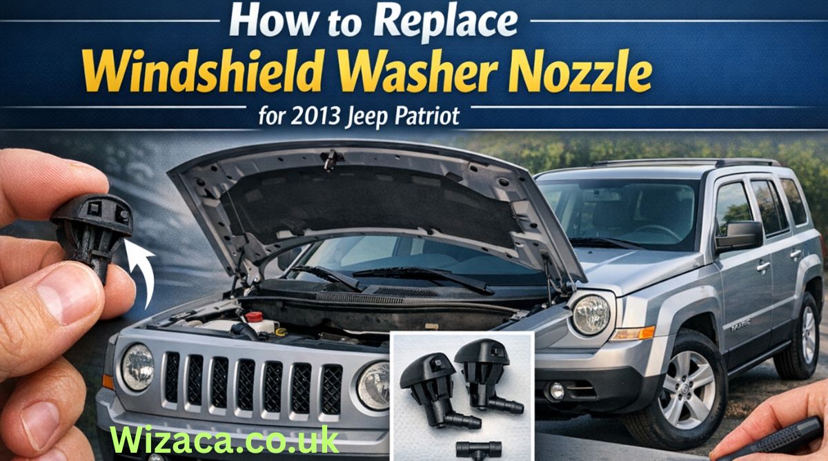
The 2013 Jeep Patriot is known for its rugged design, versatility, and ease of maintenance. One of the common maintenance tasks for the 2013 Jeep Patriot involves replacing the windshield washer nozzles. Windshield washer nozzles are small but critical components that ensure clear visibility by spraying washer fluid onto the windshield. Over time, these nozzles may become clogged, misaligned, or damaged, reducing their effectiveness. Knowing how to replace them properly not only restores optimal functionality but also contributes to overall vehicle safety. how to replace the windshield washer nozzle for a 2013 Jeep Patriot, along with tips for maintenance and troubleshooting.
Understanding Windshield Washer Nozzles
Windshield washer nozzles are designed to direct washer fluid onto the windshield in a controlled spray pattern. They are connected to the washer fluid reservoir via flexible tubing and are usually mounted on the hood or the wiper arms. The 2013 Jeep Patriot uses dual nozzles positioned on the hood to ensure even coverage across the windshield. Over time, debris, dirt, or mineral deposits from the washer fluid can clog the nozzles. Physical damage from accidents, collisions, or hoods being struck during maintenance can also necessitate replacement. Understanding the structure and function of the nozzle helps ensure the replacement is done correctly and prevents future problems.
Tools and Materials Required
Before beginning the replacement process, it is important to gather all necessary tools and materials. For the 2013 Jeep Patriot, these typically include a flathead screwdriver, needle-nose pliers, a replacement windshield washer nozzle set compatible with the 2013 model, and optionally a small towel to catch washer fluid spills. Having the proper tools ensures that the replacement is efficient and avoids accidental damage to the hood, tubing, or other components. Ensuring the replacement nozzles are genuine or compatible with Jeep specifications guarantees proper fitment and spray performance.
Preparing the Vehicle
Safety and preparation are crucial steps before starting any maintenance task. Begin by parking the Jeep Patriot on a flat, stable surface and turning off the engine. Engage the parking brake to prevent accidental movement. Open the hood fully and secure it with the hood prop rod. It is advisable to wear gloves to protect your hands from washer fluid and sharp edges under the hood. Also, placing a small towel or rag beneath the nozzles can help catch any washer fluid that may spill during the replacement process, preventing staining on the engine or hood.
Locating the Windshield Washer Nozzles
The windshield washer nozzles on the 2013 Jeep Patriot are mounted on the hood, near the base of the windshield. Each nozzle connects to the washer fluid tubing that runs from the washer fluid reservoir. To locate the nozzles, visually inspect the hood and trace the tubing from the reservoir to the nozzle outlets. Identifying the correct nozzles ensures that the replacement targets the appropriate components and avoids unnecessary disassembly of other parts. Taking a photo of the existing setup before removal can serve as a reference during installation.
Removing the Old Nozzle
Once the nozzles are located, the next step is removal. Use a flathead screwdriver or needle-nose pliers to gently pry the nozzle from its mounting hole on the hood. Be careful not to scratch or dent the hood surface. Detach the washer fluid tubing connected to the nozzle by pressing on the release clip or carefully pulling it off. Keep track of the tubing orientation, as reinstalling it incorrectly can affect spray direction and functionality. In some cases, debris may have accumulated around the nozzle, so cleaning the area with a damp cloth ensures a smooth fit for the new nozzle.
Inspecting and Cleaning the Tubing
Before installing the new nozzle, inspect the washer fluid tubing for any cracks, blockages, or damage. Clogged tubing can reduce fluid flow even after nozzle replacement. If necessary, flush the tubing with clean water or compressed air to remove any debris. Ensuring that the tubing is clean and intact prevents future issues and prolongs the life of the new nozzle. Also, check the washer fluid reservoir for adequate fluid levels and clean the reservoir cap to prevent contamination.
Installing the New Nozzle
Installation of the new windshield washer nozzle is straightforward but requires precision. Insert the nozzle into the hood mounting hole, ensuring it snaps securely into place. Reconnect the washer fluid tubing to the new nozzle, making sure it is firmly attached. The orientation of the nozzle should align with the windshield to produce an even spray pattern. Gently test the nozzle to verify that it fits snugly without tilting or wobbling. Proper installation prevents leaks, misdirected sprays, and damage during hood closure.
Testing the New Nozzle
After installing the new nozzles, testing is essential to confirm correct functionality. Fill the washer fluid reservoir if necessary and activate the windshield washer system from the control stalk inside the vehicle. Observe the spray pattern and coverage on the windshield. Adjust the nozzle angle if needed by gently moving the nozzle tip with a small tool or your fingers to ensure even fluid distribution. Ensuring that both nozzles provide consistent coverage across the windshield enhances visibility and driver safety.
Common Issues and Troubleshooting
Even after replacement, some issues may arise. If the nozzles do not spray properly, check for blockages in the tubing or incorrect nozzle alignment. Air bubbles in the tubing can sometimes prevent proper fluid flow; running the washer system for a few seconds often resolves this. Ensure that the washer fluid pump is functioning correctly and that the reservoir contains sufficient fluid. Re-check the connections to confirm that they are secure and free from leaks. Regular inspection and maintenance can prevent these common issues and maintain optimal performance.
Tips for Maintaining Windshield Washer Nozzles
Maintaining the windshield washer nozzles of your 2013 Jeep Patriot is crucial for long-term functionality. Use filtered or distilled washer fluid to prevent mineral buildup that can clog nozzles. Avoid using the washer system on dry glass, as debris or dirt can scratch the windshield and damage the nozzle tip. Regularly inspect the nozzles for cracks or misalignment, especially after extreme weather conditions or car washes. Keeping the hood and nozzle area clean prevents debris accumulation and ensures consistent performance.
When to Replace Windshield Washer Nozzles
Understanding when to replace the nozzles can save time and prevent driving hazards. Replace nozzles if the spray pattern becomes irregular, if fluid leaks from the nozzle base, or if physical damage is visible. Clogged nozzles that cannot be cleaned effectively also require replacement. Timely replacement ensures that the windshield washer system functions correctly, contributing to safer driving conditions, particularly during rain, snow, or dusty environments.
Advantages of Proper Nozzle Replacement
Replacing windshield washer nozzles properly offers several advantages. It restores clear visibility by ensuring an even spray of washer fluid, improves overall vehicle safety, and prevents long-term damage to the windshield caused by improper cleaning. Additionally, proper installation avoids unnecessary strain on the washer pump and extends the lifespan of the entire windshield washer system. Ensuring correct function also provides peace of mind during travel and enhances the overall maintenance of the 2013 Jeep Patriot.
Conclusion
Replacing the windshield washer nozzle for a 2013 Jeep Patriot is a straightforward maintenance task that significantly impacts vehicle safety and visibility. By understanding the function of the nozzles, gathering the necessary tools, preparing the vehicle, carefully removing the old nozzles, inspecting and cleaning tubing, installing new nozzles, and thoroughly testing them, Jeep owners can maintain an effective washer system. Regular inspection and proper maintenance prevent future problems and ensure that the windshield remains clean and clear under all driving conditions. Following these steps ensures that the windshield washer system operates reliably and provides the safety benefits intended by the vehicle’s design. Proper care of this small but essential component demonstrates attention to vehicle maintenance and contributes to the longevity and performance of the 2013 Jeep Patriot.

how to remove cls450 front bumper cover forum

How to Rent a Wurlitzer Piano in Athens GA

How to Repair Code U110B on a 09 Mercedes E350
Can You Rent a Storage Unit for a Month?
Does FedEx Work on Black Friday?

Does Air Have a Mass?
-
 Gaming2 weeks ago
How to Sign Up on ETSGamevent
-
 Technology2 weeks ago
How to Use CPT Upgrade in gem5: Complete Step-by-Step Guide
-
 Home Improvement2 weeks ago
How to Switch Out HZ311 Thermostat for Ecobee Premium Thermostat
-
 Technology2 weeks ago
How to Tell a Bad Plate on Flex Printing
-
 Technology2 weeks ago
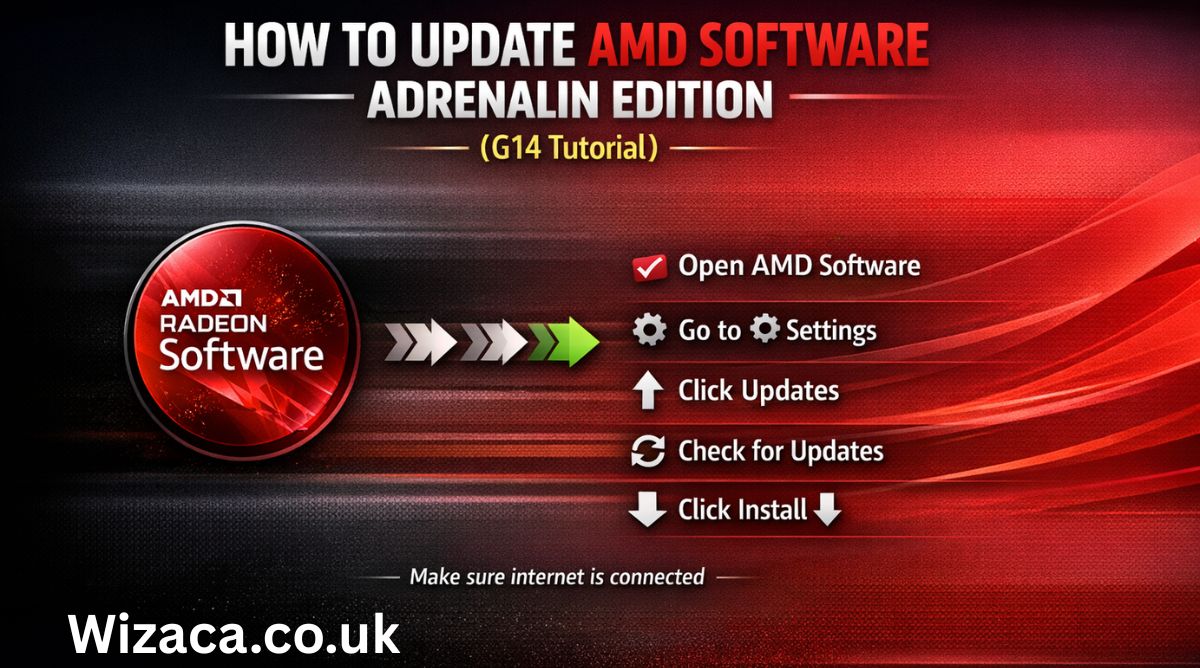
How to Update AMD Software Adrenalin Edition G14
-

 Technology2 days ago
How to Set Honuras Time Zone on a WR20BAR G-Shock
-

 Automotive1 day ago
How to Replace Windshield Washer Nozzle for 2013 Jeep Patriot
-

 Automotive1 day ago
How to Replace Transmission Seal on A1078 Corvette