
Blog
VT1000 Pitting Photo Examples: Causes, Identification, and Practical Insights
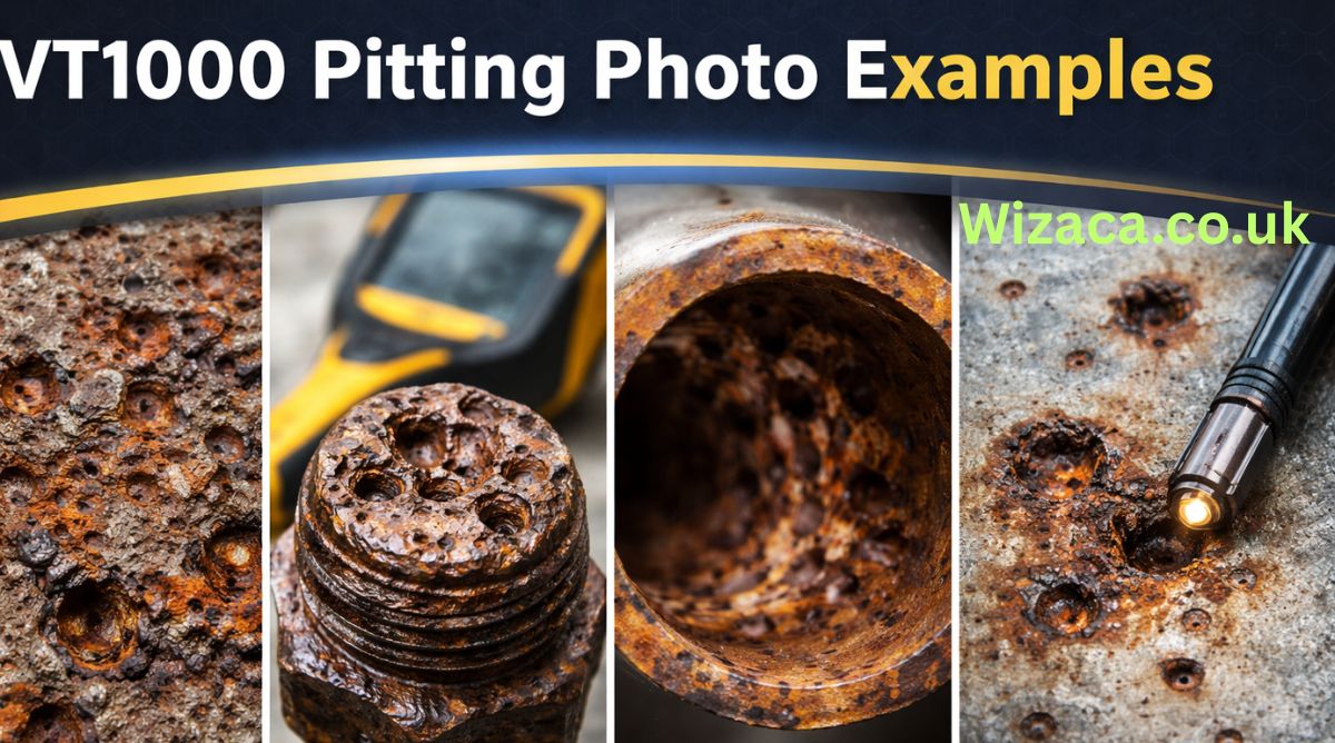
Pitting corrosion is one of the most insidious and localized forms of metal degradation observed in industrial materials. For those working with alloys such as the VT1000 series (a hypothetical high-performance alloy used in advanced industrial environments), understanding pitting corrosion is essential. Although this article does not present actual photos, it provides detailed descriptive examples of what pitting looks like and how practitioners interpret those visuals in real-world situations.
how it appears in photographs, what causes the specific patterns that engineers and inspectors observe, how to differentiate pitting from other surface damage, and how knowledge of these visual indicators informs material maintenance and failure prevention.
What Is Pitting Corrosion?
Pitting corrosion is a highly localized form of corrosion that leads to the formation of small holes or cavities on a metal surface. Unlike uniform corrosion that affects broad areas, pitting starts at microscopic sites and can deepen rapidly, often under crevices or deposits. Because pits can be difficult to detect early and can grow deeper faster than they widen, they are especially dangerous in load-bearing components.
In the case of VT1000, an alloy engineered for strength and oxidation resistance, pitting is not common under normal conditions — but when it does occur, it often signals an environmental or material stressor that must be addressed.
Why Photographic Examples Matter
Photographs are powerful tools in corrosion analysis because they capture the detailed morphology of degrading surfaces. Pitting pits are not uniform; they vary in shape, size, and distribution. By studying multiple photographic examples, technicians and engineers learn to recognize patterns, compare severity, and correlate visual cues with underlying causes.
Although this article does not display actual images, the description of pitting features mimics what professionals label and annotate when reviewing photos during inspections.
Typical Visual Features of Pitting on VT1000
When inspecting a photograph of a VT1000 surface exhibiting pitting, several common features stand out:
Concentrated Cavities or Depressions
The most recognizable sign of pitting is the presence of distinct cavities — small but deep compared to the surrounding surface. In a photo, these look like tiny craters.
Imagine a metal panel viewed at close range, with clusters of small dimples across a few square centimeters. These pits break the surface continuity but may be narrow at the opening and extend deep below the surface.
Darkened Edges Around Pits
Pitting often leaves contrasting coloration around the pits. In VT1000 examples, the areas immediately surrounding the pit mouths can appear darker or slightly discolored compared to the untouched alloy.
On photographic examples, this contrast helps inspectors distinguish pitting from scratches, machining marks, or dents.
Varied Pit Sizes
Pitting rarely produces perfectly uniform holes. A typical photograph might show a range of pit diameters — some barely visible to the naked eye, others large enough to cast tiny shadows in directional light.
For example, in a 50-millimeter section of VT1000 surface, you might see pits ranging from 0.5 millimeters to 2 millimeters in width.
Clustered vs Distributed Patterns
In some cases, pitting appears as clusters — groups of pits in a localized zone. In other cases, pits are distributed more evenly across a surface. Photographs often reveal these patterns, and careful interpretation helps determine whether localized contaminants, design geometry, or environmental exposure contributed to the issue.
Subsurface Corrosion Indications
In advanced cases, beneath shallow pits, darker subsurface lines may show where corrosion has etched deeper channels. In photos taken at an angle, these channels sometimes catch light differently, signaling hidden damage.
Example Description: Shallow Surface Pitting
In a typical photographic example of shallow surface pitting on VT1000, the inspector may note:
- Small dimples covering a 10-square-centimeter area
- Pit depths appearing no more than 0.1 millimeters
- No visible cracking or flaking
- Darkened borders contrasting against the bright alloy surface
These features suggest early-stage pitting, often associated with surface contamination or inconsistent cleaning practices. In photographs, shallow pits create a stippled effect, like the texture on lightly sanded metal.
Example Description: Deep Localized Pits
A more severe example captured in a photo might show:
- Individual pits up to 3 millimeters deep
- Narrow pit mouths, indicating rapid undercutting
- Clustering near edges or seams
- Subsurface corrosion channels visible at pit bases
Deep pits like these are more dangerous because they can significantly reduce cross-sectional strength without obvious surface indication. In photographs, these often appear as shadowed cavities under directional lighting, providing visual depth cues.
Example Description: Pitting Under Deposits
Another common example appears in photos where contaminants or deposits mask underlying pitting:
- Surface deposits of dust or residue covering most of the alloy
- After partial removal of deposits, clusters of pits become visible
- Pits appear darker and deeper compared to surrounding clean surface
- Edges of pits may show slight buildup of deposit byproducts
These examples illustrate how real-world surfaces may hide corrosion until cleaned or exposed carefully.
Example Description: Pitting Adjacent to Weld Zones
In a photo of a welded VT1000 component, the following might be observed:
- Pits concentrated near the heat-affected zone (HAZ) of the weld
- Fewer pits on the base metal farther from the weld
- Pit shapes elongated parallel to weld seams
- Slight discoloration indicating thermal stress effects
Weld-adjacent pitting often points to residual stresses or changes in microstructure affecting corrosion resistance.
Example Description: Pitting in Moisture Accumulation Areas
Some photos show pitting in areas where moisture tends to collect:
- Low points on curved surfaces showing dense pitting
- Vertical areas with drip lines showing isolated pit trails
- Slight gradients of pit size increasing toward lower edges
These examples align with environmental exposure — prolonged contact with water or condensate encourages pitting initiation.
Distinguishing Pitting from Other Surface Damage
In many practical cases, analysts must distinguish pitting from other surface irregularities that appear in photographs. Common confusions include:
Scratches vs Pits
Scratches form linear marks, whereas pits are localized depressions with depth. In photos, scratches often show as elongated lines of uniform contrast, while pits appear as individual dots with darker centers.
Machining Marks vs Pitting
Machining marks are patterned and consistent — they follow the tooling direction. Pitting is random, with irregular spacing and inconsistent size.
Dents vs Pits
Dents result from impact and usually have smooth, broad depressions. Pits are more angular, with sharper edges at their mouths.
How Lighting Affects Pitting Photographs
Photography of pitting is strongly influenced by lighting conditions. Professionals often use directional lighting to cast shadows that reveal pit depth.
Top Lighting
Top lighting can flatten visual contrast but helps highlight surface discoloration patterns.
Side Lighting
Lighting at a low angle emphasizes depth by casting shadows inside pits. This makes them more visible and easier to measure visually.
Diffused Lighting
Soft lighting helps reduce glare on bright alloy surfaces, making subtle pits easier to distinguish from shiny reflections.
Interpretation Challenges in VT1000 Pitting Photos
VT1000, like many high-performance alloys, can reflect light strongly, making small defects hard to see in photos. Proper exposure and focus are crucial.
Inexperienced observers may misinterpret glare or surface texture as pitting. Thus technicians use controlled lighting and often take multiple photographs from different angles.
Tools Used Alongside Photos for Better Assessment
Photographs are often paired with:
- Magnified imaging to measure pit dimensions
- Profile scans to chart surface topology
- Contrast enhancement to differentiate pits from surrounding alloy
These tools help convert visual evidence into quantifiable data.
Correlating Photo Features with Failure Modes
Experienced professionals learn to correlate pit appearance with underlying causes. For example:
- Many small, shallow pits often point to uniform exposure to an aggressive environment.
- Few deep pits near welds suggest localized material vulnerability.
- Pits under deposits suggest maintenance or surface cleanliness issues.
Photographic interpretation goes beyond “what it looks like” and informs “why it happened.”
Example Scenario: Pitting from Chloride Exposure
A common real-world example comes from environments with chloride exposure (such as coastal or de-icing agents). In a described photo:
- Pits appear concentrated on horizontal surfaces
- Residue patterns consistent with salt deposits
- Higher pit density near fastener heads or joints
This pattern indicates chloride-induced localized corrosion, a common risk factor for alloys like VT1000 when protective films are compromised.
Example Scenario: Pitting from Stress Concentration
In parts under mechanical stress, such as near bends or load points, pitting photos might show:
- Elongated or irregular pit shapes
- Pit clusters aligned with stress lines
- Increased depth compared to surface area
These visual indicators suggest a combination of mechanical stress and environmental attack.
Pit Depth and Structural Implications
Photographic examples often include depth context. While shallow pits may pose little immediate risk, deeper pits reduce the effective cross-section and can act as initiation points for cracking under load.
In VT1000, engineers look at how pit depth in photos correlates with load zones. Deep pits near high-stress areas trigger more urgent inspection and mitigation.
How Photos Influence Maintenance Decisions
Photos of pitting help determine:
- Whether parts can be cleaned and reused
- Whether replacement is necessary
- If protective coatings failed
- If environmental controls need improvement
These decisions are based on visual severity and distribution, informed by photographic evidence.
Communicating Findings with Photographic Records
Photographs become part of inspection reports. Annotated examples show pit size ranges, affected zones, and comparison with standard tolerance thresholds. Clear images make communication between field technicians and design engineers more effective.
Best Practices for Taking Pitting Photos
Quality photographic documentation involves:
- Controlled lighting
- Consistent scale references
- Multiple angles
- Close-up macro views
- Background contrast to enhance visibility
These practices ensure images are useful for analysis and comparison.
Training Staff to Recognize Pitting in Photos
Workshops and training modules often include annotated photo sets showing:
- Early-stage pitting
- Advanced pitting
- Pits under deposits
- Pitting adjacent to stress points
Training improves recognition and reduces misinterpretation.
Prevention Strategies Informed by Photo Analysis
Patterns in pitting photos guide preventive strategies, such as:
- Improving surface coatings
- Enhancing cleaning routines
- Reducing exposure to chlorides
- Adding drainage to prevent moisture pooling
- Redesigning stress concentration zones
Photos provide visual evidence that directs practical action plans.
Conclusion
Pitting corrosion is a serious mode of material degradation, particularly in high-performance alloys like VT1000. Photographic examples — even when described rather than shown — help professionals identify, interpret, and respond to pitting. Understanding the visual cues associated with pit shape, depth, distribution, and context enables better decision-making.
By combining photographic interpretation with technical knowledge of material behavior, environmental exposure, and mechanical stress, engineers and technicians can anticipate problems, plan maintenance, and extend service life. Mastering how pitting appears in photos is not merely an academic exercise; it is an essential skill for ensuring safety, reliability, and performance in industrial systems.

The KARR security system is a sophisticated vehicle and property protection solution designed to provide users with advanced control, monitoring, and anti-theft features. Popular among car owners and property managers, KARR systems offer features such as remote start, immobilization, alarm notifications, and keyless entry. While the system is generally user-friendly, understanding how to operate it effectively ensures maximum protection, convenience, and longevity. This article provides a comprehensive guide on how to use the KARR security system, covering setup, key functions, troubleshooting, maintenance, and best practices.
Understanding the KARR Security System
KARR security systems are electronic devices that integrate multiple security functions into one platform. They typically include:
- Central Control Module: The brain of the system that manages sensors, alarms, and communication with remote controls.
- Remote Key Fobs: Handheld devices that allow the user to arm or disarm the system, activate alarms, and remotely start vehicles if supported.
- Sensors and Detectors: Components such as door sensors, shock sensors, motion sensors, and tilt sensors that detect unauthorized access or tampering.
- Alarms and Sirens: Audible alerts designed to deter intruders and notify owners of security breaches.
- Immobilization Features: Functions that prevent the engine from starting or disable certain electrical components in case of unauthorized access.
The KARR security system is designed to protect both vehicles and property by providing real-time alerts, active deterrence, and remote monitoring capabilities.
Advantages of Using KARR Security System
- Enhanced Security: The system combines multiple security features to protect against theft, break-ins, and unauthorized access.
- Remote Access: Users can control the system remotely through key fobs, mobile apps (if supported), or other interfaces.
- Convenience Features: Many KARR systems include remote start, keyless entry, and customizable alarm settings.
- Customizable Alerts: The system can provide notifications for tampering, unauthorized movement, or impact detection.
- Integration Capability: Some KARR models can be integrated with additional sensors, GPS modules, or home security systems for comprehensive protection.
Understanding these benefits helps users appreciate the full potential of the system and encourages proper usage.
Preparing the KARR Security System for Use
Before using a KARR security system, certain preparations are necessary to ensure proper operation.
Installation Check
Verify that the system is installed correctly, whether it is a vehicle or property setup. Proper installation ensures that all sensors, wiring, and modules are functioning correctly. Improper installation can lead to false alarms, malfunctions, or reduced effectiveness.
Power Source Verification
Ensure that the system is connected to a reliable power source. For vehicles, the KARR system is usually wired to the car battery and ignition system. For property systems, ensure that the unit is connected to a stable electrical supply and, if applicable, a backup battery.
Remote Control Preparation
Familiarize yourself with the remote key fobs or mobile interfaces. Ensure that the batteries are fully charged or replaced if necessary. Having functional remotes is critical for arming, disarming, and activating features like remote start.
Familiarize with the Manual
Reading the official user manual or documentation provided with the KARR system is essential. The manual provides detailed instructions for setup, configuration, and use, as well as troubleshooting tips. Knowing these details reduces the likelihood of errors and ensures optimal system performance.
Using the KARR Security System: Basic Functions
Once the system is prepared, understanding the basic functions is the next step.
Arming and Disarming the System
Arming the system activates all sensors and prepares the system to respond to unauthorized access. This can be done via the remote key fob or control interface. Disarming deactivates the sensors and allows normal operation of the vehicle or property.
Steps for Arming:
- Press the arm button on the remote or interface.
- Observe the indicator lights or audible confirmation that the system is armed.
Steps for Disarming:
- Press the disarm button on the remote.
- Confirm that the system has disengaged through indicator lights or audible signals.
Using Remote Start (If Available)
Many KARR systems include remote start functionality for vehicles, allowing users to start the engine without physically entering the car. This feature can be useful in extreme weather conditions or for pre-heating the engine.
Steps for Remote Start:
- Ensure the vehicle is in park with the parking brake engaged.
- Press the remote start button on the key fob.
- Wait for confirmation signals, such as blinking lights or engine sound, indicating that the engine has started.
Alarm Activation and Response
The alarm system is a key component of KARR security. When a sensor detects unauthorized access, it triggers audible alarms and may send notifications. Users should be familiar with responding to alarms:
- Identify the source of the alarm through visual or audible indicators.
- Use the remote to disarm the system if authorized access is verified.
- Check for any potential tampering or damage caused by an attempted intrusion.
Using Immobilization Features
The immobilizer prevents unauthorized engine starts or disables certain functions. Engaging this feature adds an additional layer of protection.
Steps for Using Immobilizer:
- Ensure the system is armed before activating immobilization.
- Follow the remote or control interface instructions to engage or disengage the immobilizer.
- Verify functionality by testing the engine start in a controlled environment.
Sensor Management
KARR systems often allow customization of sensor sensitivity and zones. Proper configuration reduces false alarms while maintaining security.
Steps for Sensor Management:
- Access the system settings through the remote interface or control panel.
- Adjust sensitivity levels according to environmental conditions.
- Test sensors to ensure accurate detection without frequent false triggers.
Advanced Features and Settings
KARR security systems may offer advanced settings depending on the model:
- Two-Way Communication: Some systems provide feedback to the remote, confirming the status of the vehicle or property.
- Panic Mode: Allows the user to activate the alarm manually in case of immediate danger.
- Silent Arm/Disarm: Enables silent operation without audible signals for discreet security.
- Integration with GPS Tracking: Provides location monitoring for vehicles or property if equipped with GPS modules.
Understanding and using these features maximizes the functionality of the KARR security system.
Troubleshooting Common Issues
Even with proper usage, users may encounter issues. Common problems include:
Remote Not Responding
- Check the battery in the key fob and replace if necessary.
- Ensure the remote is within the operational range.
- Re-sync the remote with the control module following manufacturer instructions.
False Alarms
- Adjust sensor sensitivity to match the environment.
- Check for loose wiring or improperly installed sensors.
- Ensure environmental factors such as vibrations or pets are accounted for in sensor placement.
System Not Arming
- Verify power supply and check for blown fuses or disconnected wires.
- Ensure the immobilizer or other features are not preventing arming.
- Consult the manual for system reset procedures if necessary.
Alarm Does Not Trigger
- Check sensor connections and test each sensor individually.
- Ensure that settings for alarm triggers are correctly configured.
- Replace faulty sensors or control modules if required.
Maintaining Your KARR Security System
Regular maintenance ensures long-term reliability and effectiveness.
- Check Battery Levels: Both in the remote and backup systems.
- Clean Sensors: Remove dust, dirt, or obstructions that may affect detection.
- Test System Regularly: Arm and disarm, test remote start, and check alarms to ensure functionality.
- Update Firmware: If supported, keep system software up to date for improved performance and security features.
Best Practices for Using KARR Security System
- Always arm the system when leaving the vehicle or property.
- Customize sensor sensitivity to reduce false alarms without compromising security.
- Replace remote batteries regularly to ensure responsiveness.
- Avoid tampering with wiring or control modules, as this may reduce effectiveness or void warranty.
- Use immobilization features in combination with alarms for maximum protection.
Conclusion
The KARR security system offers comprehensive protection for vehicles and properties, combining alarms, sensors, immobilization, and remote control features. Proper understanding of system functions, careful installation, regular maintenance, and correct use of advanced features are critical to maximizing its effectiveness. Users who follow best practices can enjoy enhanced security, convenience, and peace of mind while minimizing the risk of false alarms or malfunctions.
By familiarizing themselves with arming and disarming procedures, remote start functionality, sensor management, and troubleshooting, users can leverage the full capabilities of the KARR security system. With consistent attention to maintenance, firmware updates, and battery care, the system can provide reliable protection over the long term, ensuring safety for both vehicles and property.

YELL51‑OUZ4 is a term people often search for when they want to understand how to use a specific item, tool, or product that is identified by that code. This guide explains in clear and practical detail what YELL51‑OUZ4 is generally understood to be, how it works, how to prepare for its use, how to apply it in real situations, important safety precautions, common mistakes to avoid, and tips to get the best results. The goal of this article is to provide a complete understanding of how to use YELL51‑OUZ4 in a way that is easy to follow and useful for readers.
What YELL51‑OUZ4 Is
When people refer to YELL51‑OUZ4, they are usually talking about a chemical‑based cleaning and stain‑removal solution designed to help remove tough residues from different types of surfaces. The concept behind products with codes like this is typically consistent: they contain cleaning agents that break down stubborn dirt, oils, stains, adhesives, or buildup that ordinary household cleaners cannot remove easily.
These types of products are made to be strong yet usable on a variety of materials. They are formulated in a way that allows the active ingredients to penetrate and dissolve unwanted materials so they can be wiped or rinsed away. Depending on the exact composition, YELL51‑OUZ4 can be used on surfaces like tile, metal, glass, concrete, fabric, and other items that require deep cleaning.
Why You Might Need YELL51‑OUZ4
There are many everyday scenarios where stronger cleaning solutions are necessary. For example, kitchens and bathrooms often accumulate grease and mineral deposits that regular detergents can’t handle. In automotive or workshop settings, tools and equipment may collect oil or paint splatters that need a more powerful solution. Outdoor surfaces like patios and concrete walkways can develop stubborn stains from weather exposure.
In all of these situations, a formulated cleaner labeled YELL51‑OUZ4 helps by breaking down these tough residues, making it easier to remove them without excessive scrubbing. People also use such products when preparing surfaces for repainting, refinishing, or restoration work, because it helps ensure the new material adheres properly.
How YELL51‑OUZ4 Works
Understanding how YELL51‑OUZ4 works helps you use it more effectively. Cleaning solutions of this type usually rely on a combination of chemical agents that can dissolve or loosen the bonds between dirt and the surface. These agents are designed to interact with different types of contaminants, such as:
- Oils and greases
- Ink and dye stains
- Paint or varnish residues
- Mineral deposits from hard water
- Rust or oxidation spots
- Adhesives and tape residues
When applied correctly, these cleaning agents weaken the attachment of the stain or residue, which allows it to be wiped or rinsed away more easily. These kinds of products are stronger and more concentrated than everyday soaps, so they should be used with intention and care.
Preparing to Use YELL51‑OUZ4
Proper preparation is important before applying YELL51‑OUZ4. Taking the right safety and setup steps will make the cleaning process more effective and prevent damage or irritation.
Identify the Surface
First, determine what kind of surface you’re planning to treat. Surfaces range from highly durable materials like stone or metal to delicate ones like fabric or painted wood. Some materials tolerate stronger cleaners better than others, so identifying the surface helps you adjust your approach.
Protect Surrounding Areas
If you are working near other surfaces that should not be cleaned with a strong solution, consider protecting them with tape, cloth, or covering sheets. This prevents accidental splashes or drips from affecting nearby finishes.
Ventilate the Area
Good ventilation is key when using chemical cleaning products. Open windows and doors or use a fan to ensure fresh air can circulate. Ventilation reduces the concentration of fumes and makes the cleaning process safer and more comfortable.
Wear Protective Gear
Because products like YELL51‑OUZ4 may contain strong cleaning agents, it is highly recommended to wear protective gloves. Eye protection is also advisable if there is a risk of splashing. Clothing that covers exposed skin helps avoid irritation.
Test on a Small Area
Before applying the product across a large or visible area, always test it on a small, inconspicuous spot. This patch test tells you whether the surface reacts poorly, shows discoloration, or becomes damaged. If any negative effect is observed, discontinue use on that surface.
Step‑by‑Step Instructions for Using YELL51‑OUZ4
The following steps provide a structured process to follow when using YELL51‑OUZ4 for tough stains and deep cleaning.
Step One: Clear the Area
Remove loose debris, dust, or dirt from the surface. Use a dry cloth, brush, or vacuum to remove anything that might interfere with the cleaning process. Removing loose material helps the cleaner work more directly on the stain itself.
Step Two: Apply the Product to the Stain
Apply the cleaner directly to the problem area. If the product is liquid, pour or spray it carefully so that the stain is fully covered. For thicker or semi‑solid stains, use enough liquid to saturate the surface without creating excessive runoff.
Step Three: Let It Penetrate
Allow the solution to sit on the stain for a period of time. The exact duration depends on how stubborn the stain is, but typically five to ten minutes is sufficient for most applications. This waiting period lets the cleaning agents break down the stain bonds.
Step Four: Gently Agitate the Surface
After allowing the cleaner to work, gently scrub or agitate the surface with a soft brush or cloth. For hard surfaces, a brush with moderate bristles helps loosen dissolved residue. For softer materials, a gentle cloth is recommended to avoid damage.
Step Five: Wipe or Rinse Away
Once the stain has been loosened, wipe the area with a clean cloth. For some surfaces, you may need to rinse with clean water to ensure all cleaning agents and residue are fully removed. After rinsing, dry the surface thoroughly.
Step Six: Repeat if Necessary
Stubborn stains may require a second application. If the first attempt did not fully remove the residue, repeat the steps above until the stain is gone. Always allow the surface to dry between applications so you can accurately assess how much cleaner is still needed.
Special Considerations for Different Surfaces
When using YELL51‑OUZ4, the type of surface you are cleaning affects how you should approach it. Some materials are more resilient, while others require extra care.
Hard Surfaces
Surfaces like tile, stone, concrete, and metal tolerate strong cleaners well. Apply the product, allow it to work, and then scrub with a medium‑firm brush. After cleaning, rinse with water and dry. Hard surfaces usually handle repeated applications without damage.
Glass Surfaces
Glass can be cleaned effectively, but avoid abrasive brushes that can scratch. Use soft cloths for application and removal. Wiping with a dry cloth after rinsing helps prevent streaks.
Fabrics and Upholstery
Delicate fabrics are sensitive to strong cleaners. Use a minimal amount of product, and avoid soaking the material. After treating the stain, rinse gently and allow to air dry. Always conduct a patch test first.
Painted or Finished Wood
Surfaces with paint or sealant may discolor or weaken if exposed to strong chemical cleaners. Apply the product only where necessary and use very light agitation. If any damage occurs, stop immediately.
Safety Precautions
Using a chemical cleaner like YELL51‑OUZ4 safely involves more than just following the application steps. Safety precautions reduce the risk of irritation, harm, or accidental damage.
Wear Personal Protective Equipment
Always wear gloves to protect your skin. Eye protection is recommended when splashes are likely. Avoid direct contact with untreated skin.
Work in a Ventilated Area
Fumes from powerful cleaning products can be irritating if inhaled in a confined space. Proper ventilation disperses fumes and creates a safer environment.
Keep Out of Reach of Children and Pets
Strong cleaners should be stored securely where children or pets cannot access them. Accidental ingestion or skin contact can pose serious health risks.
Handle Spills Carefully
If the product spills, clean it up immediately with absorbent material. Dispose of any waste according to local regulations. Never leave spills unattended, especially on floors or surfaces people walk on.
Common Mistakes to Avoid
Avoiding mistakes ensures a more effective and safer cleaning process.
Using Excessive Amounts
Applying too much cleaner does not speed up the cleaning process. Instead, use only what is needed to cover the stain and follow the recommended dwell time. Overuse can make rinsing more difficult and may leave residue.
Not Testing First
Skipping the patch test increases the risk of damaging the surface. Always test first, even if the material seems durable.
Scrubbing Too Hard
Strong scrubbing on delicate surfaces can cause scratches, discoloration, or wear. Use gentle motions on soft materials and appropriate brushes on hard ones.
Ignoring Warning Signs
If a surface begins to discolor or react negatively during cleaning, stop immediately. Continuing can cause permanent damage that may be difficult or expensive to reverse.
Tips for Best Results
To maximize the effectiveness of YELL51‑OUZ4, consider these tips:
- Work in small sections so you can focus on each stain thoroughly.
- Allow adequate dwell time for the cleaner to penetrate the stain.
- Rinse and dry surfaces fully to prevent residue buildup.
- Use the appropriate tool (cloth, brush, or sponge) for the surface type.
- Maintain regular cleaning so stubborn stains do not develop in the first place.
Final Thoughts
Learning how to use YELL51‑OUZ4 effectively means understanding the nature of the surface, preparing properly, applying the product carefully, and following through with correct safety procedures. With proper technique, a product like YELL51‑OUZ4 helps remove tough stains and deeply embedded dirt that ordinary cleaners cannot handle.
This guide provides a complete walkthrough of the process, from preparation and application to safety and maintenance. By following these instructions, anyone can use YELL51‑OUZ4 in a practical and informed way to achieve the best possible cleaning results.

The phrase 40.0 UHF 2G EchoStar Technologies LLC 186217 appears technical and complex at first glance, but it represents an important combination of wireless communication concepts, regulatory identifiers, and industrial technology practices. This topic is often associated with radio frequency usage, satellite and communication hardware, legacy cellular standards, and manufacturer identification within regulated systems.
This in-depth article explains the meaning, context, and relevance of 40.0 UHF, 2G technology, EchoStar Technologies LLC, and the numeric identifier 186217.
Introduction to Technical Identifiers in Communication Systems
Modern communication systems rely heavily on precise technical identifiers. These identifiers help engineers, regulators, and manufacturers track frequencies, equipment capabilities, and compliance standards.
A string such as 40.0 UHF 2G EchoStar Technologies LLC 186217 combines multiple layers of information into a compact reference that can be used across technical, regulatory, and operational contexts.
Understanding the Meaning of 40.0 in Communication Contexts
The value 40.0 typically refers to a measurement or specification within a technical system. In radio and communication environments, numeric values like this may relate to power levels, bandwidth, signal parameters, or configuration settings.
Such values are not arbitrary; they are chosen to meet performance requirements while remaining within regulatory limits.
Overview of UHF Frequency Band
UHF stands for Ultra High Frequency. It is a portion of the electromagnetic spectrum commonly used for wireless communication, broadcasting, and data transmission.
UHF frequencies are known for their balance between range and data-carrying capability. They penetrate buildings better than higher frequencies and are less susceptible to interference than lower-frequency bands.
Role of UHF in Modern Communication Systems
UHF plays a crucial role in many communication applications. These include broadcasting signals, two-way radios, satellite downlinks, and various industrial communication systems.
The use of UHF allows systems to maintain reliable connectivity across diverse environments, including urban, rural, and mobile settings.
Interpreting 2G Technology
The term 2G refers to second-generation cellular technology. It represents an early stage of digital mobile communication that replaced analog systems.
2G networks introduced digital voice transmission, improved call quality, and basic data services. Although newer generations have largely replaced 2G, it remains relevant in specific industrial and legacy applications.
Why 2G Is Still Used in Certain Systems
Despite the advancement of 3G, 4G, and newer technologies, 2G continues to be used in some specialized contexts. Its advantages include low power consumption, wide coverage, and simplicity.
For machine-to-machine communication, remote monitoring, and legacy hardware, 2G can remain a practical solution.
Combination of UHF and 2G Concepts
When UHF and 2G appear together, it often suggests a system that blends radio frequency transmission with cellular-era communication standards.
Such systems may be used for control signaling, telemetry, or data exchange in environments where newer technologies are unnecessary or impractical.
Introduction to EchoStar Technologies LLC
EchoStar Technologies LLC is a well-known entity in the field of satellite communication and related technologies. The company has historically been involved in the design, manufacturing, and deployment of communication equipment.
Its name is frequently associated with satellite systems, receivers, transmitters, and infrastructure supporting broadcast and data services.
EchoStar’s Role in Communication Hardware Development
EchoStar has contributed to advancements in communication hardware by integrating radio frequency engineering with digital signal processing.
Equipment associated with EchoStar often reflects a focus on reliability, scalability, and compliance with regulatory standards.
Industrial and Commercial Applications of EchoStar Systems
EchoStar-related systems are used in a variety of applications, including broadcasting, remote communication, and specialized data transmission environments.
These systems are designed to operate efficiently over long distances and under varying environmental conditions.
Significance of the Numeric Identifier 186217
The number 186217 functions as an identifier. In technical and regulatory contexts, numeric identifiers are used to distinguish specific devices, filings, certifications, or configurations.
Such identifiers help ensure accurate documentation and traceability across systems and organizations.
Purpose of Equipment and Filing Identifiers
Identifiers like 186217 allow engineers and regulators to reference exact equipment models or approval records without ambiguity.
They support compliance verification, maintenance tracking, and lifecycle management of communication systems.
Regulatory Environment for UHF and 2G Systems
UHF frequencies and 2G technologies operate within regulated environments. Authorities define how frequencies can be used to prevent interference and ensure public safety.
Manufacturers and operators must design systems that meet these regulatory requirements.
Compliance and Certification Processes
Before communication equipment can be deployed, it typically undergoes testing and certification. These processes verify that the equipment operates within allowed frequency ranges and power limits.
Identifiers such as 186217 often appear in documentation related to these approvals.
Technical Architecture of UHF-Based Systems
UHF systems rely on antennas, transmitters, receivers, and control units. Each component must be precisely engineered to maintain signal quality and stability.
The integration of these components determines overall system performance.
Signal Characteristics in UHF Communication
UHF signals are known for moderate range and good penetration. They are suitable for environments where obstacles such as buildings or terrain would limit higher-frequency signals.
These characteristics make UHF a preferred choice for many practical communication applications.
Power and Efficiency Considerations
Systems operating at UHF and using 2G-era technologies often emphasize efficiency. Lower power consumption reduces operational costs and extends equipment lifespan.
This is especially important in remote or continuously operating systems.
Reliability in Long-Term Operations
One reason legacy technologies remain in use is reliability. Mature systems like 2G have well-understood behavior and predictable performance.
For mission-critical applications, stability can be more important than cutting-edge speed.
Integration with Other Communication Systems
UHF and 2G-based systems may operate alongside newer technologies. Hybrid setups allow organizations to balance legacy compatibility with modern capabilities.
Such integration requires careful planning and engineeringा

how to install a duralast fuel filter ff831dl

how to make scent beads for laundry

how to make fruit and veggie wash
Can You Rent a Storage Unit for a Month?
How to Use KARR Security System: A Complete guide

Does Air Have a Mass?
-

 Beauty1 week ago
how to make your own cleansing oil
-

 Automotive2 weeks ago
How to Replace Windshield Washer Nozzle for 2013 Jeep Patriot
-

 Education1 week ago
how to print a report card in powerschool
-

 Electronics1 week ago
how to pair 2 jbl eon 715 speakers together
-

 Technology2 weeks ago
How to Set Honuras Time Zone on a WR20BAR G-Shock
-

 Automotive2 weeks ago
How to Replace Transmission Seal on A1078 Corvette
-

 Cleaning16 hours ago
how to make bath towels soft again
-

 Automotive2 weeks ago
How to Repair Code U110B on a 09 Mercedes E350