
Automotive
1999 Impreza Lever Shifter Assembly: A Complete guide
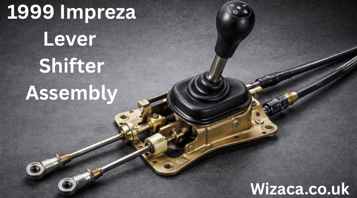
The 1999 Impreza lever shifter assembly is a critical mechanical component that directly affects how the driver interacts with the vehicle’s transmission. In manual transmission models especially, the shifter assembly plays a major role in gear selection, driving comfort, responsiveness, and overall driving feel. Understanding how this assembly works, its components, common issues, maintenance needs, and upgrade possibilities is essential for owners, mechanics, and automotive enthusiasts.
Introduction to the 1999 Impreza Lever Shifter Assembly
The lever shifter assembly is the physical mechanism that connects the driver’s hand movements to the transmission. In the 1999 Impreza, this system was designed with durability and simplicity in mind, balancing cost-effective engineering with reliable performance.
Although it may appear simple from the cabin, the shifter assembly is a carefully engineered system involving multiple mechanical parts working together to ensure smooth and accurate gear changes.
Importance of the Shifter Assembly in Vehicle Operation
The shifter assembly is essential because it translates driver input into mechanical action within the transmission. A properly functioning shifter ensures accurate gear engagement, minimizes wear, and enhances driving control.
Key roles of the shifter assembly include:
- Selecting gears accurately
- Providing tactile feedback to the driver
- Maintaining alignment with transmission linkages
Any issue in this system can significantly affect drivability.
Overview of the 1999 Impreza Transmission System
The 1999 Impreza commonly came with a manual transmission option, making the lever shifter assembly especially important. The shifter does not directly engage gears but operates through linkages that connect to the transmission selector mechanism.
This indirect system allows flexibility, vibration isolation, and smoother shifting under varying driving conditions.
Main Components of the Lever Shifter Assembly
The lever shifter assembly is composed of several interconnected parts, each serving a specific function.
Primary components include:
- Shift lever
- Pivot ball
- Bushings
- Shift linkage rods
- Retaining clips and fasteners
Each part must function correctly for smooth gear selection.
The Shift Lever Design and Function
The shift lever is the visible and most frequently used part of the assembly. In the 1999 Impreza, the lever is typically made of metal for strength and durability.
The lever’s length and angle influence:
- Shift throw distance
- Driver comfort
- Shift precision
A balanced design ensures ease of use and responsiveness.
Pivot Ball and Its Mechanical Role
The pivot ball sits near the base of the shift lever and allows it to move freely in multiple directions. This spherical joint is critical for enabling the lever to engage different gear positions.
Wear in the pivot ball can cause:
- Excessive play
- Loose shifting feel
- Reduced accuracy
Proper lubrication and fit are essential.
Bushings and Their Importance
Bushings are small components, often made of rubber or plastic, that reduce vibration and friction between moving parts.
In the 1999 Impreza shifter assembly, bushings:
- Isolate vibrations from the transmission
- Improve shift smoothness
- Maintain proper alignment
Over time, worn bushings are one of the most common causes of sloppy shifting.
Shift Linkage Rods Explained
The shift linkage rods connect the lever assembly to the transmission selector shaft. These rods transmit motion and determine how accurately gear changes occur.
Properly aligned linkage rods ensure:
- Precise gear engagement
- Reduced transmission wear
- Consistent shifting behavior
Bent or worn rods can lead to misalignment.
Retaining Clips and Mounting Hardware
Small but crucial, retaining clips and fasteners keep the assembly securely connected. These parts prevent unwanted movement and maintain structural integrity.
Failure of clips or fasteners can cause:
- Sudden loss of shift control
- Increased noise
- Unsafe driving conditions
They must always be properly installed.
How the Lever Shifter Assembly Works
When the driver moves the shift lever, the motion pivots around the pivot ball and transfers through the linkage rods to the transmission. The transmission then engages the selected gear.
This process requires:
- Precise alignment
- Minimal friction
- Secure mounting
Any looseness reduces shift quality.
Driving Feel and Shift Feedback
The 1999 Impreza is known for offering a relatively direct and mechanical shift feel. The lever shifter assembly plays a major role in this characteristic.
Good shift feedback provides:
- Confidence during gear changes
- Better control during spirited driving
- Clear indication of gear engagement
Worn components reduce this feedback.
Common Wear Issues in the Shifter Assembly
Over time, normal use causes wear in various parts of the shifter assembly.
Common wear-related problems include:
- Loose or sloppy shifter
- Difficulty engaging certain gears
- Increased vibration
These issues often develop gradually.
Symptoms of a Failing Shifter Assembly
Drivers may notice several signs indicating shifter assembly problems.
Typical symptoms include:
- Excessive side-to-side movement
- Grinding during gear changes
- Unusual noises when shifting
Early diagnosis helps prevent further damage.
Causes of Shifter Assembly Problems
Several factors contribute to wear and failure.
Common causes include:
- High mileage
- Aggressive shifting habits
- Lack of maintenance
Environmental factors such as dirt and moisture can also accelerate wear.
Inspection of the Lever Shifter Assembly
Regular inspection helps identify issues before they become severe.
Inspection typically involves:
- Checking for looseness
- Inspecting bushings for cracks
- Ensuring fasteners are secure
A visual and physical inspection can reveal many issues.
Maintenance Practices for Longevity
Proper maintenance extends the life of the shifter assembly.
Recommended practices include:
- Periodic lubrication
- Replacing worn bushings
- Tightening loose components
Preventive maintenance improves shifting quality.
Lubrication Requirements
Lubrication reduces friction between moving parts and prevents premature wear.
Proper lubrication:
- Improves smoothness
- Reduces noise
- Protects metal surfaces
Using appropriate lubricants is essential.
Replacement of Worn Bushings
Bushing replacement is one of the most effective ways to restore shift feel.
Benefits of new bushings include:
- Reduced play
- Improved precision
- Enhanced driving experience
This is a common maintenance task.
Adjustment of the Shifter Assembly
Proper adjustment ensures correct alignment between the lever and transmission.
Adjustment improves:
- Gear engagement accuracy
- Shift smoothness
- Driver confidence
Misadjustment can cause gear selection issues.
Removal of the Lever Shifter Assembly
Removing the shifter assembly typically involves accessing it from inside the cabin and underneath the vehicle.
Careful removal prevents:
- Damage to components
- Loss of small hardware
- Misalignment during reinstallation
Attention to detail is critical.
Reinstallation and Alignment
Correct reinstallation ensures proper function.
Key steps include:
- Aligning linkage rods
- Securing all fasteners
- Verifying gear engagement
Improper installation can worsen shifting issues.
Aftermarket vs Stock Shifter Assemblies
Some owners choose aftermarket components to improve shift performance.
Differences include:
- Shorter shift throws
- Firmer feel
- Increased precision
However, stock assemblies prioritize comfort and longevity.
Impact of Driving Style on Shifter Wear
Driving habits significantly affect shifter assembly lifespan.
Aggressive shifting can:
- Accelerate bushing wear
- Stress linkage components
- Increase maintenance needs
Smooth shifting extends component life.
Cold Weather Effects on the Shifter Assembly
Cold temperatures can stiffen lubricants and bushings.
Cold weather effects include:
- Increased shift resistance
- Delayed smoothness
- Temporary stiffness
Proper lubrication helps mitigate this.
Noise and Vibration Issues
Noise or vibration during shifting often indicates worn or loose components.
Common sources include:
- Worn bushings
- Loose mounting points
- Dry pivot joints
Addressing noise early prevents further damage.
Safety Considerations
A faulty shifter assembly can pose safety risks.
Potential risks include:
- Inability to select gears
- Unexpected gear disengagement
- Loss of vehicle control
Prompt repair is essential for safe driving.
Cost Factors Associated with Shifter Repairs
Repair costs vary depending on the components involved.
Factors affecting cost include:
- Extent of wear
- Replacement parts required
- Labor complexity
Preventive maintenance reduces expenses.
Restoration of Original Shift Feel
Many owners aim to restore the factory shift feel of the 1999 Impreza.
Restoration typically involves:
- Replacing worn components
- Proper lubrication
- Correct alignment
This returns the vehicle to its intended driving experience.
Long-Term Reliability of the Shifter Assembly
With proper care, the original shifter assembly can last many years.
Long-term reliability depends on:
- Maintenance habits
- Driving conditions
- Component quality
Durability is a key strength of the design.
Compatibility with Other Impreza Models
Some components may be shared with other Impreza years, but differences exist.
Compatibility considerations include:
- Design variations
- Mounting differences
- Linkage length
Correct parts selection is important.
Benefits of a Well-Maintained Shifter Assembly
A properly maintained assembly offers numerous advantages.
Benefits include:
- Smooth gear changes
- Improved control
- Enhanced driving enjoyment
Maintenance directly improves performance.
Driving Experience and Driver Confidence
A responsive shifter enhances driver confidence, especially in manual transmissions.
Confidence improves:
- Driving precision
- Enjoyment
- Overall vehicle control
The shifter is central to this experience.
Mechanical Simplicity of the 1999 Impreza Design
The 1999 Impreza lever shifter assembly reflects a mechanically simple yet effective design.
Simplicity offers:
- Easier maintenance
- Fewer failure points
- Long-term durability
This is one reason for its popularity.
Final Thoughts on the 1999 Impreza Lever Shifter Assembly
The 1999 Impreza lever shifter assembly is a vital mechanical system that directly influences driving quality, control, and safety. Although it may not receive as much attention as the engine or transmission, its condition has a major impact on the overall driving experience.
Understanding its components, operation, common issues, and maintenance requirements allows owners to keep their vehicle performing at its best. With regular inspection, proper lubrication, and timely replacement of worn parts, the shifter assembly can continue to deliver smooth, precise, and reliable gear changes for many years.

Activating a Karr security system is a crucial step in ensuring your vehicle remains protected against theft and unauthorized access. Karr is known for its reliable car alarm systems, keyless entry features, and immobilizers. Proper activation allows the system to function optimally, providing peace of mind to vehicle owners. This guide will cover all aspects of activating Karr security systems, including preparation, installation verification, programming, troubleshooting, and best practices for use.
understanding karr security systems
Karr security systems are designed to provide comprehensive vehicle protection through a combination of alarms, immobilizers, and remote control functionalities. These systems typically include:
- Car Alarm: Detects unauthorized entry or movement of the vehicle.
- Keyless Entry: Allows remote locking and unlocking of the vehicle.
- Immobilizer: Prevents the vehicle from starting without the proper key or remote signal.
- Shock Sensors: Detects impacts or vibrations to trigger the alarm.
- Remote Control: Enables activation and deactivation of the system from a distance.
Understanding the components of your Karr system is essential before attempting activation, as different models may have varying features and steps for programming.
prerequisites for activating karr security systems
Before activating your Karr security system, ensure the following:
- Battery Power: Verify that the vehicle’s battery and the remote control battery are fully charged.
- Correct Installation: Ensure that the system is installed correctly and all wires are connected according to the manufacturer’s instructions.
- User Manual: Have the system’s user manual available for reference, as activation procedures can differ between models.
- Vehicle Readiness: Make sure doors, hood, and trunk are closed, and the ignition is in the OFF position.
- Remote Control: Ensure the remote control is compatible with the installed system.
Meeting these prerequisites ensures that the activation process is smooth and avoids unnecessary errors.
locating the activation button or switch
Most Karr security systems have a hidden activation button or switch inside the vehicle, which is used to program the system and pair the remote control. Common locations include:
- Under the dashboard near the steering column.
- Inside the center console or glove compartment.
- Near the fuse box or ignition wiring.
Refer to the system’s manual for the exact location, as pressing the correct button is necessary to enter programming mode.
entering programming mode
To activate your Karr security system, you must first enter programming mode. The steps generally include:
- Turn the Ignition On: Insert the key into the ignition and turn it to the ON position without starting the engine.
- Press the Activation Button: Press and hold the hidden activation button until the system’s LED indicator flashes or a sound confirms entry into programming mode.
- Release the Button: Release the button once the system acknowledges the mode entry, often through one long beep or flashing lights.
Programming mode allows you to pair remote controls, set security options, and adjust system preferences.
pairing remote controls
Once in programming mode, the next step is pairing your remote controls to the Karr system:
- Press Remote Button: Press a specific button on the remote, usually the lock or unlock button, to transmit its signal to the system.
- Confirmation: The system will acknowledge the pairing with a sound, flash, or LED indicator.
- Repeat for Additional Remotes: If you have more than one remote, repeat the pairing process for each device.
Successful pairing ensures that only authorized remotes can operate the system.
testing the karr system
After activation and pairing, it is essential to test the system:
- Lock and Unlock: Use the remote to lock and unlock the doors and verify that the alarm responds.
- Alarm Trigger: Activate the alarm manually to ensure it responds to shocks or unauthorized entry.
- Remote Range: Test the remote at various distances to confirm optimal signal transmission.
- Ignition Immobilizer: Attempt to start the vehicle without the remote to ensure the immobilizer is functioning correctly.
Testing confirms that the system is fully operational and provides maximum security.
troubleshooting common activation issues
During activation, you may encounter problems. Common issues include:
- Remote Not Pairing: Check battery power, ensure you are in programming mode, and verify compatibility with your Karr system.
- System Not Responding: Confirm correct wiring and that the vehicle’s battery is fully charged.
- False Alarms: Adjust shock sensor sensitivity settings to prevent accidental triggers.
- LED Indicator Not Flashing: Replace the system’s fuse or check connections to ensure power is reaching the control unit.
Following the manual and these troubleshooting steps resolves most common activation problems.
customizing system settings
After activation, you can customize Karr system settings to match your preferences:
- Shock Sensor Sensitivity: Adjust to prevent false alarms while maintaining protection.
- Alarm Duration: Set how long the alarm sounds when triggered.
- Remote Functions: Enable or disable features such as trunk release, panic button, or silent arm/disarm.
- Automatic Locking: Program doors to lock automatically after a specific time.
Customizing these settings ensures your security system meets your specific needs.
maintaining your karr security system
Proper maintenance helps keep your Karr system in peak condition:
- Battery Check: Regularly check the vehicle and remote batteries.
- Clean Components: Keep buttons, sensors, and wiring free from dust and moisture.
- Software Updates: If your system supports updates, install them as provided by the manufacturer.
- Professional Service: Periodically have a certified technician inspect the system to ensure functionality.
Routine maintenance prolongs the life of your security system and prevents malfunctions.
conclusion
Activating a Karr security system requires careful attention to installation, programming, and testing. By understanding the components, entering programming mode correctly, pairing remotes, and customizing settings, vehicle owners can maximize protection against theft and unauthorized access. Regular maintenance and troubleshooting ensure the system remains reliable over time, providing peace of mind and effective vehicle security. Following this guide allows users to confidently activate their Karr security systems and enjoy the full benefits of advanced car protection technology.

Learning how to install a Duralast fuel filter FF831DL properly is essential for maintaining your vehicle’s fuel system performance and engine efficiency. The Duralast Fuel Filter FF831DL is designed to trap dirt, rust particles, and other contaminants before they reach the fuel injectors or carburetor. Over time, fuel filters become clogged, restricting fuel flow and causing symptoms such as engine hesitation, poor acceleration, rough idling, or difficulty starting. Replacing the fuel filter at recommended intervals helps maintain proper fuel pressure and ensures smooth engine operation. Understanding the tools required, safety precautions, and correct installation steps will allow you to complete the task safely and effectively.
Understanding the Purpose of a Fuel Filter
Before focusing on how to install a Duralast fuel filter FF831DL, it is important to understand its function. Fuel travels from the fuel tank to the engine through fuel lines. During this process, contaminants such as debris, rust flakes, and sediment may enter the system. The fuel filter acts as a barrier, preventing these impurities from reaching sensitive engine components. A clogged filter reduces fuel flow, which can negatively affect performance and fuel economy. Replacing it restores proper flow and protects internal engine parts.
Identifying the Correct Location
The location of the fuel filter varies depending on the vehicle. In many cars and light trucks, the inline fuel filter is mounted along the fuel line under the vehicle, often near the fuel tank or along the frame rail. In some vehicles, it may be located inside the engine compartment. Before beginning installation, consult your vehicle’s service manual to identify the exact placement. Correct identification ensures safe access and efficient replacement.
Tools and Materials Needed
To successfully complete how to install a Duralast fuel filter FF831DL, gather necessary tools before starting. Common tools include safety gloves, protective eyewear, a jack and jack stands if access underneath is required, fuel line disconnect tools if applicable, wrenches, a container to catch spilled fuel, clean rags, and the replacement fuel filter. Having everything prepared reduces interruptions and increases safety.
Safety Precautions Before Starting
Fuel systems are pressurized, and gasoline is highly flammable. Before working on the fuel system, relieve fuel pressure. This can often be done by removing the fuel pump fuse and running the engine until it stalls. Turn off the ignition afterward. Disconnect the negative battery terminal to reduce the risk of sparks. Work in a well ventilated area away from open flames or heat sources. Keep a fire extinguisher nearby as an added safety measure.
Raising the Vehicle if Necessary
If the fuel filter is mounted underneath the vehicle, lift the vehicle using a jack and secure it with jack stands on a stable surface. Never rely solely on a jack for support. Ensure the vehicle is stable before crawling underneath. Safety during this stage is critical when learning how to install a Duralast fuel filter FF831DL.
Locating the Existing Fuel Filter
Once access is available, locate the existing inline fuel filter. It is typically cylindrical and connected between two sections of fuel line. Note the direction of fuel flow indicated by an arrow on the old filter. The new filter must be installed in the same orientation to ensure proper function.
Preparing for Removal
Place a container beneath the filter to catch any residual fuel. Even after relieving pressure, some fuel may remain in the lines. Use clean rags to minimize spillage. If your vehicle uses quick connect fittings, use the appropriate disconnect tool to release the fuel lines. For threaded fittings, use the correct size wrench to avoid damaging the fittings.
Removing the Old Fuel Filter
Carefully disconnect the fuel lines from both ends of the old filter. Avoid bending or twisting the lines excessively. Once disconnected, remove the mounting bracket or retaining clip holding the filter in place. Gently remove the old filter and allow any remaining fuel to drain into the container. Dispose of the old filter according to local environmental regulations.
Comparing the New Filter
Before installation, compare the new Duralast fuel filter FF831DL to the old one. Ensure the inlet and outlet fittings match in size and design. Confirm that the overall length and connection style are identical. This step prevents installation errors and ensures compatibility.
Installing the New Fuel Filter
Position the new filter in the mounting bracket with the arrow indicating fuel flow pointing toward the engine. This orientation is crucial. Secure the filter in its bracket firmly but do not overtighten to avoid damage. Reconnect the fuel lines to the appropriate ends. If using quick connect fittings, push until you hear or feel a click indicating secure attachment. For threaded fittings, tighten them carefully without cross threading.
Rechecking Connections
After installation, double check all connections to ensure they are tight and properly seated. Loose fittings can lead to fuel leaks. Inspect the mounting bracket to confirm the filter is stable and not contacting other components.
Restoring Fuel System Pressure
Reconnect the negative battery terminal. Reinstall the fuel pump fuse if it was removed. Turn the ignition key to the on position for a few seconds without starting the engine. This primes the fuel system and restores pressure. Turn the key off and repeat this process two or three times to ensure proper pressure buildup.
Checking for Leaks
Start the engine and inspect the area around the filter for any signs of leakage. Look closely at both connections and the body of the filter. If you notice fuel dripping or smell gasoline strongly, turn off the engine immediately and tighten connections as needed. Ensuring there are no leaks is an essential part of how to install a Duralast fuel filter FF831DL safely.
Lowering the Vehicle
If the vehicle was lifted, carefully remove the jack stands and lower it back to the ground once you confirm there are no leaks. Ensure all tools and containers are removed from underneath before lowering.
Testing Vehicle Performance
After installation, take the vehicle for a short test drive. Pay attention to acceleration, idle smoothness, and overall responsiveness. A properly installed new fuel filter should improve fuel flow and may resolve previous performance issues related to fuel restriction.
Maintenance Interval
Fuel filters typically require replacement every 20000 to 40000 miles, depending on manufacturer recommendations and driving conditions. Regular replacement prevents fuel system damage and maintains efficiency. Check your vehicle’s maintenance schedule for specific guidance.
Common Mistakes to Avoid
When learning how to install a Duralast fuel filter FF831DL, avoid skipping the pressure relief step. Never install the filter backward. Do not overtighten fittings, as this can strip threads or damage lines. Avoid working near open flames. Ensure the vehicle is securely supported if raised.
Benefits of Proper Installation
Correct installation ensures consistent fuel pressure, better engine performance, improved fuel efficiency, and reduced strain on the fuel pump. A clean filter helps protect injectors from clogging and extends the life of the fuel system.
Final Thoughts
Understanding how to install a Duralast fuel filter FF831DL allows vehicle owners to perform essential maintenance safely and effectively. By following proper safety precautions, relieving fuel pressure, carefully removing the old filter, installing the new filter in the correct orientation, checking for leaks, and testing performance afterward, you can maintain a reliable and efficient fuel system. Regular inspection and timely replacement of the fuel filter help ensure smooth engine operation and long term vehicle reliability.

If you are searching for how to remove cls450 front bumper cover forum discussions, you are likely looking for detailed, practical guidance from owners and enthusiasts who have already performed the job. The CLS450 is part of the luxury CLS lineup from Mercedes-Benz, and while it offers refined styling and advanced technology, even premium vehicles occasionally require maintenance, repairs, or cosmetic upgrades. Removing the front bumper cover may be necessary for tasks such as replacing a damaged grille, installing a new sensor, repairing impact damage, upgrading lighting components, or repainting the bumper.
The Mercedes-Benz CLS450 features a modern front fascia design with integrated sensors, parking assistance systems, and sleek LED lighting. Because of this complexity, removing the bumper cover requires patience, the correct tools, and an understanding of how the components are assembled. Many forum users emphasize taking your time and documenting each step with photos to ensure smooth reinstallation.
Understanding the CLS450 Front Bumper Structure
Before starting the removal process, it is important to understand how the bumper is constructed. The CLS450 front bumper consists of a plastic outer cover attached to a reinforced internal structure. The cover is secured with screws, bolts, plastic clips, and fasteners along the top, bottom, and inside the wheel wells.
Modern models often include integrated components such as parking sensors, radar units for driver assistance systems, air intake ducts, and fog light housings. Disconnecting these properly is essential to prevent damage.
Forum discussions frequently highlight that the bumper cover is not extremely heavy, but it is wide and somewhat flexible. Having a second person assist during removal helps avoid bending or scratching the painted surface.
Tools Required for the Job
When reviewing how to remove cls450 front bumper cover forum advice, most users recommend gathering the proper tools before beginning. Typically, you will need a socket wrench set with metric sockets, a Torx bit set, plastic trim removal tools, a flathead screwdriver, and possibly a Phillips screwdriver. A trim clip removal tool is especially helpful to avoid breaking plastic fasteners.
It is also recommended to have a soft blanket or foam pad ready to place the bumper cover on once removed. This prevents paint scratches or scuffs.
Safety gloves are useful to protect your hands from sharp plastic edges or metal brackets. Good lighting is important as well, especially when working inside the wheel arches.
Preparing the Vehicle
Preparation is a crucial step. Park the vehicle on a flat surface and engage the parking brake. Turning the steering wheel fully to one side provides better access to the wheel well fasteners. Some forum members suggest removing the front wheels entirely for maximum space, though this is optional.
Disconnecting the battery may be advisable if you will be unplugging electronic sensors or radar modules. This reduces the risk of triggering warning lights or short circuits.
Opening the hood allows access to the upper mounting points of the bumper cover. These are typically located along the radiator support area.
Removing the Upper Fasteners
Under the hood, you will find several screws or bolts securing the top edge of the bumper to the front support structure. Carefully remove these using the appropriate socket or Torx bit.
Forum users often recommend placing all removed hardware in labeled containers to keep track of different screw lengths and types. Losing or mixing up fasteners can complicate reinstallation.
Once the upper bolts are removed, the bumper cover will still be secured at the sides and bottom.
Detaching Wheel Well Fasteners
Next, focus on the wheel wells. Inside each front wheel arch, there are multiple screws and plastic clips attaching the bumper cover to the fender liner.
Using a trim removal tool helps avoid damaging the clips. Gently pull back the fender liner to expose hidden screws securing the side edges of the bumper.
Many forum contributors note that this area can be tight, so patience is essential. Avoid pulling forcefully, as the painted tabs connecting the bumper to the fender can break if stressed.
Removing Lower Screws and Splash Shield Connections
Underneath the vehicle, the bumper cover connects to the lower splash shield and undertray. Remove the screws or bolts securing these sections.
In some models, additional fasteners are positioned near the front lip or air dam. Carefully inspect the entire lower edge before attempting to pull the bumper away.
Failing to remove a hidden fastener can result in cracked plastic tabs.
Disconnecting Electrical Components
One of the most important steps mentioned in how to remove cls450 front bumper cover forum threads is properly disconnecting electrical connectors. The CLS450 often includes front parking sensors, a front camera, radar sensors for adaptive cruise control, and LED daytime running lights.
Once the bumper is partially loosened, gently pull it forward a few inches and reach behind to unplug connectors. Press the release tabs carefully and avoid yanking wires.
Labeling connectors with tape can help during reinstallation, especially if multiple plugs look similar.
Removing the Bumper Cover
With all fasteners removed and connectors unplugged, the bumper cover can be detached. This step is best done with assistance. Each person should hold one side and gently pull outward at the corners near the fenders to release the side clips.
After releasing the sides, carefully pull the bumper forward and away from the vehicle. Place it on a prepared soft surface to prevent damage.
Forum members frequently emphasize checking once more for any missed connectors or clips before fully separating the bumper.
Common Challenges and Troubleshooting
Some users report difficulty with stubborn clips near the headlights. Applying gentle outward pressure while lifting slightly can help release these tabs.
Another common issue involves broken plastic retaining clips. Replacement clips are relatively inexpensive and should be replaced if damaged to ensure secure reinstallation.
If warning lights appear after reinstallation, they may be related to improperly connected sensors. Double-check all electrical connections before assuming a more serious issue.
Reinstallation Tips
Reinstalling the bumper cover follows the reverse order of removal. Position the bumper carefully and reconnect all electrical connectors before fully securing it.
Align the side tabs with the fender slots and press firmly until they click into place. Install lower screws and splash shield fasteners first to support the bumper’s weight.
Next, secure the wheel well screws and clips, ensuring the fender liner is properly aligned. Finally, tighten the upper bolts under the hood.
Do not overtighten screws, as this can strip plastic mounting points.
When to Seek Professional Help
Although many enthusiasts successfully remove the bumper themselves, some situations warrant professional assistance. If your vehicle is equipped with advanced driver assistance systems requiring sensor recalibration, a certified technician may be necessary.
Complex radar units integrated into the front fascia sometimes require precise alignment after removal. Incorrect positioning can affect adaptive cruise or collision prevention systems.
Additionally, if the bumper removal is related to accident damage, hidden structural components may need inspection.
Importance of Forum-Based Knowledge
The phrase how to remove cls450 front bumper cover forum reflects the value of community knowledge. Owners who share firsthand experiences provide practical insights beyond official service manuals.
Forums often include photos, step-by-step walkthroughs, and troubleshooting tips that simplify complex procedures. Reading multiple threads before beginning can prepare you for unexpected challenges.
While official repair manuals from Mercedes-Benz offer precise specifications, community advice adds real-world perspective.
Safety Considerations
Always work in a well-lit, stable environment. Avoid rushing the process. Keep hardware organized and protect painted surfaces from scratches.
If lifting the vehicle for better access, use proper jack stands rather than relying solely on a hydraulic jack.
Take extra care with delicate components such as sensors and wiring harnesses.
Final Thoughts
Searching how to remove cls450 front bumper cover forum typically means you want a practical, experience-based explanation rather than a brief overview. Removing the front bumper cover on the Mercedes-Benz CLS450 is a manageable task for those with moderate mechanical skill and patience.
Understanding the bumper’s attachment points, carefully removing fasteners, disconnecting electronic components properly, and working methodically are key to success. With preparation and attention to detail, the process can be completed safely and efficiently.
Whether your goal is repair, customization, or maintenance, following structured guidance ensures that your CLS450 remains in excellent condition while avoiding unnecessary damage or complications.

how tight do i need to torque my echelon screws

how to activate karr security systems

how to add autochartist to mt5
How to Adjust U-Haul Mirrors for Safe Driving
Can You Rent a Storage Unit for a Month?

Does Air Have a Mass?
-

 Health7 days ago
how to clean diffuser without vinegar
-

 Home Improvement7 days ago
how to clean granite before sealing
-

 Technology7 days ago
how to delete apps on kyocera 902kc flip phone
-

 Cleaning7 days ago
how to clean sofa cushion covers
-

 General3 days ago
What Is 4842570165? Complete Guide
-

 Home Improvement7 days ago
how to clean white painted woodwork
-

 Technology11 hours ago
how to change cardpop I 82v8 emmc/b to windows 11
-
 Finance11 hours ago
how to add autochartist to mt5